asokatechnologies@gmail.com 09347143789/09949240245

Search This Blog

Tuesday, 22 February 2022

A Highly Efficient and Reliable Inverter Configuration Based Cascaded Multi-Level Inverter for PV Systems

 ABSTRACT:

This paper presents an improved Cascaded Multi-Level Inverter (CMLI) based on a highly efficient and reliable configuration for the minimization of the leakage current. Apart from a reduced switch count, the proposed scheme has additional features of low switching and conduction losses. The proposed topology with the given PWM technique reduces the high-frequency voltage transitions in the terminal and common-mode voltages. Avoiding high-frequency voltage transitions achieves the minimization of the leakage current and reduction in the size of EMI filters. Furthermore, the extension of the proposed CMLI along with the PWM technique for 2m+1 levels is also presented, where m represents the number of Photo Voltaic (PV) sources. The proposed PWM technique requires only a single carrier wave for all 2m+1 levels of operation. The Total Harmonic Distortion (THD) of the grid current for the proposed CMLI meets the requirements of IEEE 1547 standard. A comparison of the proposed CMLI with the existing PV Multi-Level Inverter (MLI) topologies is also presented in the paper. Complete details of the analysis of PV terminal and common-mode voltages of the proposed CMLI using switching function concept, simulations, and experimental results are presented in the paper.

KEYWORDS:

1.      Cascaded multi-level inverter

2.      Leakage current

3.      Common-mode voltage

4.      Terminal voltage

SOFTWARE: MATLAB/SIMULINK

BLOCK DIAGRAM:


Fig. 1. Proposed five-level grid-connected CMLI with PV and parasitic elements.

 EXPECTED SIMULATION RESULTS:

Fig. 2. Simulation results of proposed five-level CMLI showing the waveforms of : (a) output voltage vuv; (b) grid current iac; (c) terminal voltage vxg; (d) terminal voltage vyg; (e) terminal voltage vzg; (f) leakage current ileak; (g) common-mode voltage vcm.

CONCLUSION:


In this paper, an improved five-level CMLI with low switch count for the minimization of leakage current in a transformerless PV system is proposed. The proposed CMLI minimizes the leakage current by eliminating the high-frequency transitions in the terminal and common-mode voltages. The proposed topology also has reduced conduction and switching losses which makes it possible to operate the CMLI at high switching frequency. Furthermore, the solution for generalized 2m+1 levels CMLI is also presented in the paper. The given PWM technique requires only one carrier wave for the generation of 2m+1 levels. The operation, analysis of terminal and common-mode voltages for the CMLI is also presented in the paper. The simulation and experimental results validate the analysis carried out in this paper. The MPPT algorithm is also integrated with the proposed five-level CMLI to extract the maximum power from the PV panels. The proposed CMLI is also compared with the other existing MLI topologies in Table V to show its advantages.

REFERENCES:

[1] Y. Tang, W. Yao, P.C. Loh and F. Blaabjerg, "Highly Reliable Transformerless Photovoltaic Inverters With Leakage Current and Pulsating Power Elimination," IEEE Trans. Ind. Elect., vol. 63, no. 2, pp. 1016-1026, Feb. 2016.

[2] W. Li, Y. Gu, H. Luo, W. Cui, X. He and C. Xia, "Topology Review and Derivation Methodology of Single-Phase Transformerless Photovoltaic Inverters for Leakage Current Suppression," IEEE Trans. Ind. Elect., vol. 62, no. 7, pp. 4537-4551, July 2015.

[3] J. Ji, W. Wu, Y. He, Z. Lin, F. Blaabjerg and H. S. H. Chung, "A Simple Differential Mode EMI Suppressor for the LLCL-Filter-Based Single-Phase Grid-Tied Transformerless Inverter," IEEE Trans. Ind. Elect., vol. 62, no. 7, pp. 4141-4147, July 2015.

[4] Y. Bae and R.Y.Kim, "Suppression of Common-Mode Voltage Using a Multicentral Photovoltaic Inverter Topology With Synchronized PWM," IEEE Trans. Ind. Elect., vol. 61, no. 9, pp. 4722-4733, Sept. 2014.

[5] N. Vazquez, M. Rosas, C. Hernandez, E. Vazquez and F. J. Perez-Pinal, "A New Common-Mode Transformerless Photovoltaic Inverter," IEEE Trans. Ind. Elect., vol. 62, no. 10, pp. 6381-6391, Oct. 2015.


Friday, 11 February 2022

A Five-Level Step-up Module for Multilevel Inverters: Topology, Modulation Strategy and Implementation


ABSTRACT:

 This paper proposes a new single-phase five-level converter based on switched capacitor technique. The capacitor charging in the proposed converter is carried out in a self-balancing form which does not need closed-loop modulations or additional balancing circuits. The proposed topology is a voltage booster without using end side H-bridge for changing load voltage polarity. So, switching losses and total voltage stress of semiconductor components reduce in the proposed converter. The performing modes of the proposed topology, its modulation scheme, capacitors’ balancing analysis, capacitance and loss calculations, and also the development of the proposed converter for enhancing the quality of output voltage waveform are discussed in depth. Moreover, the comparison of the proposed structure with the other multi-level topologies shows that the proposed converter can reduce the number of semiconductor elements and the required isolated DC sources. Finally, the simulation and experimental results validate the appropriate performance of the proposed converter.

KEYWORDS:

1.      Power conversion

2.      Multilevel converter

3.      Switched capacitor technique

4.      Self-balancing

5.      Phase disposition pulse width modulation technique

SOFTWARE: MATLAB/SIMULINK

PROPOSED DIAGRAM:


Fig. 1. Circuit arrangement of the proposed converter (VLoad = Va-Vb)

 EXPECTED SIMULATION RESULTS:


Fig. 2. Simulation results, (a) output waveforms with resistive load (ZL=50Ω) (b) output waveforms with resistive-inductive load (ZL=50Ω+100mH) (c) capacitors’ voltage (d) output voltage THD

Fig. 3. The simulation results with sudden change in the load (a) first scenario (b) second scenario (c) third scenario

Fig. 4. The simulation results of the capacitors’ voltage, output voltage and current in diode–rectifier state with R–C load (R=120Ω, C=2.2mF)


Fig. 5. (a) Modules’ output voltage (b) capacitors’ voltage (c) converter’s output voltage and current with ZL=100Ω (d) converter’s output voltage and current with ZL=100Ω+200mH

CONCLUSION:


In this paper, a single phase five-level switched-capacitor converter is proposed, which is combination of a switched capacitor cell (SCC) and two half-bridge cell (HBC). The capacitors’ charging in the proposed topology is carried out in self-balancing form and the charging time is independent of the load. The main idea of the proposed configuration is to reduce the number of power devices along with boosting capability. Compared to other five-level converters, the proposed topology reduces the number of DC power supplies, semiconductor switches, diodes, size and cost of the system. Simple configuration, easy control and voltage booster are the main benefits of the proposed converter. Operational modes of proposed topology and its modulation strategy, capacitors’ charging analysis and voltage stress of the switches, capacitance and power losses calculations are presented in depth. Finally, the operation and performance of the proposed converter are verified with experiments on a 5-level prototype.

REFERENCES:


[1] L. G. Franquelo, J. Rodriguez, J. I. Leon, S. Kouro, R. Portillo, and M. A. M. Prats, "The age of multilevel converters arrives," IEEE Industrial Electronics Magazine, vol. 2, pp. 28-39, 2008.

[2] F. Gao, "An Enhanced Single Phase Step-Up Five-Level Inverter," IEEE Trans. Power Electron., vol. PP, pp. 1-1, 2016.

[3] C. H. Hsieh, T. J. Liang, S. M. Chen, and S. W. Tsai, "Design and Implementation of a Novel Multilevel DC-AC Inverter," IEEE Trans. Ind. Appl., vol. 52, pp. 2436-2443, 2016.

[4] A. Nabae, I. Takahashi, and H. Akagi, "A New Neutral-Point-Clamped PWM Inverter," IEEE Trans. Ind. Appl., vol. IA-17, pp. 518-523, 1981.

[5] T. A. Meynard and H. Foch, "Multi-Level Choppers for High Voltage Applications," EPE Journal, vol. 2, pp. 45-50, 1992.


A dual control strategy for power sharing improvement in islanded mode of AC microgrid

ABSTRACT:

Parallel operation of inverter modules is the solution to increase the reliability, efficiency, and redundancy of inverters in microgrids. Load sharing among inverters in distributed generators (DGs) is a key issue. This study investigates the feasibility of power-sharing among parallel DGs using a dual control strategy in islanded mode of a microgrid. PQ control and droop control techniques are established to control the microgrid operation. P-f and Q-E droop control is used to attain real and reactive power sharing. The frequency variation caused by load change is an issue in droop control strategy whereas the tracking error of inverter power in PQ control is also a challenge. To address these issues, two DGs are interfaced with two parallel inverters in an islanded AC microgrid. PQ control is investigated for controlling the output real and reactive power of the DGs by assigning their references. The inverter under enhanced droop control implements power reallocation to restore the frequency among the distributed generators with predefined droop characteristics. A dual control strategy is proposed for the AC microgrid under islanded operation without communication link. Simulation studies are carried out using MATLAB/SIMULINK and the results show the validity and effective power-sharing performance of the system while maintaining a stable operation when the microgrid is in islanding mode.

KEYWORDS:

1.      Microgrid

2.      Inverter parallel operation control strategy

3.      Droop control strategy

4.      Frequency restore

5.      Power sharing

SOFTWARE: MATLAB/SIMULINK


BLOCK DIAGRAM:


Fig. 1 Enhanced droop control diagram

 EXPECTED SIMULATION RESULTS:

Fig. 2 Output voltage and current waveforms at PCC under the proposed dual –control


Fig. 3 Tracking output power of PQ control inverter

Fig. 4 Active power dynamics response at PCC

Fig. 5 Reactive power dynamics response at PCC

Fig. 6 Frequency variation with and without FRS

CONCLUSION:

 This letter proposes a compact nine-level T-type packed U-cell inverter. Compared with other nine-level inverters, the proposed topology has fewer power semiconductor devices and only needs two isolated dc sources. Furthermore, the proposed PWM scheme only uses one carrier, which can reduce the design and control complexity. Since the T-type leg will generate the high frequency switching waveform, it can be replaced by SiC MOSFETs for significantly reducing switching losses. Experimental results verified the performance of the proposed multilevel topology.

REFERENCES:

 [1] K. K. Gupta, A. Ranjan, P. Bhatnagar, L. Kumar Sahu, and S. Jain, “Multilevel inverter topologies with reduced device count: A review,” IEEE Trans. Power Electron., vol. 31, no. 1, pp. 135–151, Jan. 2016.

 [2] J. Rodriguez, S. Bernet, B. Wu, J. O. Pontt, and S. Kouro, “Multilevel voltage-source-inverter topologies for industrial medium-voltage drives,” IEEE Trans. Ind. Electron., vol. 54, no. 6, pp. 2930–2945, Dec. 2007.

[3] H. Abu-Rub, J. Holtz, J. Rodriguez, and G. Baoming, “Medium-voltage multilevel inverters: State of the art, challenges, and requirements in industrial applications,” IEEE Trans. Ind. Electron., vol. 57, no. 8, pp. 2581–2596, Aug. 2010.

[4] S. Kouro, M. Malinowski, K. Gopakumar, J. Pou, L. G. Franquelo, B. Wu, J. Rodriguez, M. A. Perez, and J. I. Leon, “Recent advances and industrial applications of multilevel converters,” IEEE Trans. Ind. Electron., vol. 57, no. 8, pp. 2553–2580, Aug. 2010.

[5] P. R. Bana, K. P. Panda, R. T. Naayagi, P. Siano, and G. Panda, “Recently Developed Reduced Switch Multilevel Inverter for Renewable Energy Integration and Drives Application: Topologies, Comprehensive Analysis and Comparative Evaluation,” IEEE Access, vol. 7, pp. 54888–54909, 2019.

A Comparative Study of Energy Management Schemes for a Fuel Cell Hybrid Emergency Power System of More Electric Aircraft

ABSTRACT:

This paper presents a comparative analysis of different energy management schemes for a fuel cell based emergency power system of a more electric aircraft. The fuel cell hybrid system considered in this study consists of fuel cells, lithium-ion batteries and supercapacitors, along with associated DC/DC and DC/AC converters. The energy management schemes addressed are state-of-the-art, most commonly used energy management techniques in fuel cell vehicle applications and include: the state machine control strategy, the rule based fuzzy logic strategy, the classical PI control strategy, the frequency decoupling/fuzzy logic control strategy and the equivalent consumption minimization strategy (ECMS). The main criteria for performance comparison are the hydrogen consumption, the state of charges of the batteries/supercapacitors and the overall system efficiency. Moreover the stresses on each energy source, which impact their life cycle, are measured using a new approach based on the wavelet transform of their instantaneous power. A simulation model and an experimental test bench are developed to validate all analysis and performances.

KEYWORDS:

1.      Fuel cells

2.       Batteries

3.      Supercapacitors

4.      DC-DC converters

5.      Energy management

6.      Hybridization

7.      Optimization

SOFTWARE: MATLAB/SIMULINK

BLOCK DIAGRAM:


Fig. 1. Overall system schematic

 EXPECTED SIMULATION RESULTS:


Fig. 2. Simulation and experimental results for all EMS schemes: (a) Simulation results. State machine control (b) Experimental results. State machine control (c) Simulation results. Rule based fuzzy logic (d) Experimental results. Rule based fuzzy logic (e) Simulation results. Classical PI control (f) Experimental results. Classical PI control (g) Simulation results. Frequency decoupling and fuzzy logic (h) Experimental results. Frequency decoupling and fuzzy logic (i) Simulation results. ECMS (j) Experimental results. ECMS

CONCLUSION:


This paper presented a performance comparison of different energy management schemes for a fuel cell hybrid emergency system of more electric aircraft. The hybrid system is modelled and validated with experiments. Five state-of-the art commonly used energy management schemes are studied through simulations and experimental tests on a 14 kW fuel cell hybrid system. The same initial condition is used for all the schemes and the experimental results are close to simulations. The criteria for performance comparison are the hydrogen consumption, the battery state of charge, the overall efficiency and the stress seen by each energy source. The latter is measured using a new approach based on wavelet transform. Compared to the other schemes, the state machine control scheme provided a slightly better efficiency (80.72%) and stresses on the battery and supercapacitor (_ of 21.91 and 34.7 respectively). The classical PI control scheme had the lowest fuel consumption (235 g of H2 consumed) and more use of the battery energy (SOC between 70 - 51 %). As expected, the lowest fuel cell stress (_ of 12.04) and lowest use of the battery energy (SOC between 70 - 59 %) was achieved with the frequency decoupling and fuzzy logic scheme, but at the expense of more fuel consumption (245 g of H2 consumed) and lower overall efficiency (79.32 %). The DC bus or supercapacitor voltage was maintained nearly constant (_ 270 V DC) for all the schemes. To conclude, the energy management system suitable for MEA should be a multi-scheme EMS such that each scheme is chosen based on a specific criterion to prioritize. As an example, depending on the operating life of each energy source, the energy management strategy can be chosen to either minimize the stress on the fuel cell system, the battery system or supercapacitor system, hence maximizing the life cycle of the hybrid power system. Also if the target is to reduce the fuel consumption, the strategy based on the classical PI or ECMS could be selected. An alternative is to design a multi-objective optimization EMS to optimize all the performance criteria, which is the next topic for further studies.

REFERENCES:


[1] P. Thounthong and S. Rael, ”The benefits of hybridization”. IEEE Ind. Electron. Mag., vol.3, no.3, pp.25-37, Sept. 2009.

[2] P. Thounthong, S. Rael and B. Davat, ”Control Strategy of Fuel Cell and Supercapacitors Association for a Distributed Generation System,” IEEE Trans. Ind. Electron., vol.54, no.6, pp.3225-3233, Dec. 2007.

[3] Z. Amjadi and S. Williamson, ”Power-Electronics-Based Solutions for Plug-in Hybrid Electric Vehicle Energy Storage and Management Systems,” IEEE Trans. Ind. Electron., vol.57, no.2, pp.608-616, Feb. 2010.

[4] G. Renouard-Vallet ,M. Saballus, G. Schmithals , J. Schirmer, J. Kallo and A. K. Friedrich, ”Improving the environmental impact of civil aircraft by fuel cell technology: concepts and technological progress,” Energy Environ. Sci., 2010,1458-1468.

[5] G. Renouard-Vallet ,M. Saballus, G. Schmithals , J. Schirmer, J. Kallo and A. K. Friedrich, ”Fuel Cells For Aircraft Applications,” ECS Trans., 2011, Volume 30, Issue 1, Pages 271-280.

Thursday, 30 December 2021

Direct Torque Control of DFIG Driven by Wind Turbine System Connected to the Grid

ABSTRACT:

This paper described a Direct Torque Control (DTC) applied to a Doubly Fed Induction Generator (DFIG) driven by a Wind Turbine (WT) connected to the grid. This control strategy based on the regulation of the flux and the torque, the currents and voltages are used to estimate the torque and the flux and compare those magnitudes to the reference values, the obtained results will be converted to digital form by hysteresis comparators. The commutation table will use those values and the sector number to choose the voltage vector. The aim of this study is to treat three modes that can drive WT-DFIG system utilizing Maximum Power Point Tracking (MPPT) technique. Computer simulation has carried out under MATALB/Simulink environment and the obtained results demonstrate the effectiveness of the proposed control.

 KEYWORDS:

1.      Direct Torque Control

2.      Doubly Fed Induction Generator

3.      Wind Turbine

4.      Wind Energy

5.      Maximum Power Point Tracking

 SOFTWARE: MATLAB/SIMULINK

 BLOCK DIAGRAM:


Fig.1. DTC Control applied to DFIG connected to the grid.

EXPECTED SIMULATION RESULTS:


Fig.2. Wind speed.

Fig.3. Cp (λ) Characteristic.

Fig.4. Mechanical speed (generator speed).


Fig.5. Waveform of Slip.


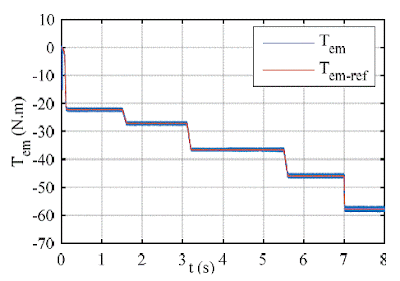
Fig.6. Electromagnetic Torque.


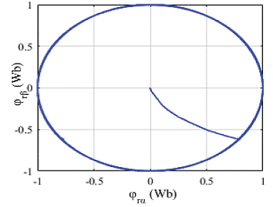
Fig.7. Rotor and Reference flux.

Fig.8. The rotor flux.


Fig.9. Wave form of Rotor flux φ and φ.

Fig.10. Rotor Current Ir(abc)


Fig.11. Rotor Reactive Power


Fig.12. Stator Current Is(abc)


Fig.13. Stator Power


Fig.14. Rotor Power

Fig.15. The FFT analysis of phase (a) stator current (Synchronous mode).

CONCLUSION:

A study of Direct Torque Control strategy applied to Doubly Fed Induction Generator used for Wind Turbine Conversation system has been presented in this paper. As known, the wind has a random movement imposing indiscriminate speed for the turbine, therefore driving DFIG in different modes (sub-synchronous, synchronous and super synchronous modes), those modes have been treated in this work. The obtained results show clearly satisfactory performances, they showed a good dynamic of the torque and the flux, low THD in synchronous mode and constant stator frequency, while keeping a better precision of control, as well as the efficiency of the control strategy leading to better performances.

REFERENCES:


[1] C. J. Nobles, E. F. Schisterman, Sandie Ha, Keewan Kim, and all, “Ambient air pollution and semen quality,” Environmental Research. 163, 2018, pp. 228-236.

[2] B. Sawetsakulanond, V. Kinnares, “Design, analysis, and construction of a small scale self-excited induction generator for wind energy application,” Energy Journal. 2010, pp. 4975–4985.

[3] A. Tapia, G. Tapia, J.X. Ostolaza, J.R. Saenz, “Modeling and control of a wind turbine driven doubly fed induction generator,” IEEE Trans. Energy Convers. 2003, pp. 194–204.

[4] “GWEC’s Global Wind Report - Annual Market Update,” the Global Wind Energy Council, 2017. Available: http://www.gwec.net.

[5] “Renewables 2017 global status report 2017,” Ren21, 2017.