asokatechnologies@gmail.com 09347143789/09949240245

Search This Blog

Sunday 7 December 2014

Fuzzy-Logic-Controller-Based SEPIC Converter for Maximum Power Point Tracking

Fuzzy-Logic-Controller-Based SEPIC Converter for
Maximum Power Point Tracking

ABSTRACT:

This paper presents a fuzzy logic controller (FLC)-based single-ended primary-inductor converter (SEPIC) for maximum power point tracking (MPPT) operation of a photovoltaic (PV) system. The FLC proposed presents that the convergent distribution of the membership function offers faster response than the symmetrically distributed membership functions. The fuzzy controller for the SEPIC MPPT scheme shows high precision in current transition and keeps the voltage without any changes, in the variable-load case, represented in small steady-state error and small overshoot. The proposed scheme ensures optimal use of PV array and proves its efficacy in variable load conditions, unity, and lagging power factor at the inverter output (load) side. The real-time implementation of the MPPT SEPIC converter is done by a digital signal processor (DSP), i.e., TMS320F28335. The performance of the converter is tested in both simulation and experiment at different operating conditions. The performance of the proposed FLC-based MPPT operation of SEPIC converter is compared to that of the conventional proportional–integral (PI)-based SEPIC converter. The results show that the proposed FLC-based MPPT scheme for SEPIC can accurately track the reference signal and transfer power around 4.8% more than the conventional PI-based system.

KEYWORDS:

1.      DC–DC power converters
2.       Fuzzy control
3.      Photovoltaic (PV) cells
4.       Proportional–integral (PI) controller
5.       Real-time system

SOFTWARE: MATLAB/SIMULINK

CIRCUIT DIAGRAM:


Fig.1.Circuit diagram of the SEPIC converter for the FLC-based MPPT scheme.

CONTROL SCHEME:


Fig.2.Overall control scheme for the proposed FLC-based MPPT scheme for the SEPIC converter.

EXPECTED SIMULATION RESULTS:


Fig.3. Output (top) voltage and (bottom) current waveforms of the SEPIC converter with the proposed FLC-based MPPT scheme.
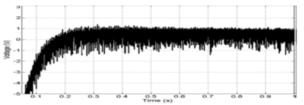


Fig. 4. Error signal (difference between Vreal and Vref ) of the proposed FLC-based SEPIC converter.
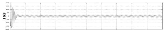

Fig. 5. Variable-load inverter current, voltage, and voltage error signals.

Fig.6. Inverter current, voltage, and voltage error signals with lagging power factor load for the proposed FLC-based SEPIC and inverter system.
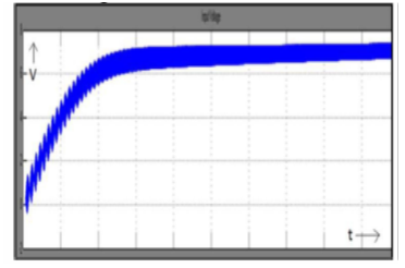

Fig.7. FLC-based SEPIC’s output voltage.


Fig. 8. Comparison of the power output for the proposed FLC- and PI-based SEPIC converters.


Fig. 9. Experimental results for Vinv and Iinv with unity power factor load.


Fig. 10. Experimental results for Vinv and Iinv with 0.766 lagging power factor load.


Fig. 11. Harmonic analysis of the current waveform in Fig. 19.

CONCLUSION:

An FLC-based MPPT scheme for the SEPIC converter and inverter system for PV power applications has been presented in this paper. A prototype SEPIC converter-based PV inverter system has also been built in the laboratory. The DSP board TMS320F28335 is used for real-time implementation of the proposed FLC and MPPT control algorithms. The performance of the proposed controller has been found better than that of the conventional PI-based converters. Furthermore, as compared to the conventional multilevel inverter, experimental results indicated that the proposed FLC scheme can provide a better THD level at the inverter output. Thus, it reduces the cost of the inverter and the associated complexity in control algorithms. Therefore, the proposed FLC-based MPPT scheme for the SEPIC converter could be a potential candidate for real-time PV inverter applications under variable load conditions.

REFERENCES:

[1] K.M. Tsang andW. L. Chan, “Fast acting regenerative DC electronic load based on a SEPIC converter,” IEEE Trans. Power Electron., vol. 27, no. 1, pp. 269–275, Jan. 2012.
[2] S. J. Chiang, H.-J. Shieh, and M.-C. Chen, “Modeling and control of PV charger system with SEPIC converter,” IEEE Trans. Ind. Electron., vol. 56, no. 11, pp. 4344–4353, Nov. 2009.
[3] M. G. Umamaheswari, G. Uma, and K. M. Vijayalakshmi, “Design and implementation of reduced-order sliding mode controller for higher-order power factor correction converters,” IET Power Electron., vol. 4, no. 9, pp. 984–992, Nov. 2011.
[4] A. A. Fardoun, E. H. Ismail, A. J. Sabzali, and M. A. Al-Saffar, “New efficient bridgeless Cuk rectifiers for PFC applications,” IEEE Trans. Power Electron., vol. 27, no. 7, pp. 3292–3301, Jul. 2012.
[5] M. Hongbo, L. Jih-Sheng, F. Quanyuan, Y. Wensong, Z. Cong, and Z. Zheng, “A novel valley-fill SEPIC-derived power supply without electrolytic capacitor for LED lighting application,” IEEE Trans. Power Electron., vol. 27, no. 6, pp. 3057–3071, Jun. 2012. 

Dynamic Behavior of DFIG Wind Turbine Under Grid Fault Conditions

Dynamic Behavior of DFIG Wind Turbine Under Grid Fault Conditions

ABSTRACT:


The use of doubly fed induction generators (DFIGs) in wind turbines has become quite common over the last few years. These machines provide variable speed and are driven with a power converter which is sized for a small percentage of the turbine-rated power. This paper presents a detailed model of induction generator coupled to wind turbine system. Modeling and simulation of induction machine using vector control computing technique is done. DFIG wind turbine is an integrated part of distributed generation system. Therefore, any abnormalities associates with grid are going to affect the system performance considerably. Taking this into account, the performance of DFIG variable speed wind turbine under network fault is studied using simulation developed in MATLAB/SIMULINK.

KEYWORDS

1.      DFIG
2.       DQ Model
3.       Vector Control


SOFTWARE: MATLAB/SIMULINK

BLOCK DIAGRAM:


Fig. 1 Simulink model of DFIG system

EXPECTED SIMULATION RESULTS:


 Time (sec)
 Fig. 2 Stator currents during balance condition


Time (sec)
           Fig. 3 Rotor currents during balance condition


                                                                                   Time (sec)
                    Fig. 4 Speed and torque during balance condition.


                                                                       Time (sec)
                     Fig. 5 Acive and reactive power during balance condition

CONCLUSION:

This paper presents a study of the dynamic performance of variable speed DFIG coupled with wind turbine. The dynamic behavior of DFIG under power system disturbance was simulated using MATLAB/SIMULINK.Accurate transient simulations are required to investigate the influence of the wind power on the power system stability. The DFIG considered in this analysis is a wound rotor induction generator with slip rings. The stator is directly connected to the grid and the rotor is interface via a back to back power converter. Power converter are usually controlled utilizing vector control techniques which allow the decoupled control of both active and reactive power flow to the grid. In the present investigation, the dynamic DFIG performance is presented for both normal and abnormal grid conditions. The control performance of DFIG is satisfactory in normal grid conditions and it is found that, both active and reactive power maintains a study pattern in spite of fluctuating wind speed and net electrical power supplied to grid is maintained constant.

REFERENCES:

[1] T. Brekken, and N. Mohan, “A novel doubly-fed induction wind generator control scheme for reactive power control and torque pulsation compensation under unbalanced grid voltage conditions”, IEEE PESC Conf Proc., Vol 2, pp. 760-764, 2003.
[2] L. Xu and Y. Wang, “Dynamic modeling and control of DFIG-based wind turbines under unbalanced network conditions”, IEEE Trans. On Power System, Vol 22, Issues 1, pp. 314-323, 2007.
[3] F.M. Hughes, O. Anaya-Lara, N. Jenkins, and G. Strbac, “Control of DFIG based wind generation for power network support”, IEEE Trans. On Power Systems, Vol 20, pp. 1958-1966, 2005.
[4] S. Seman, J. Niiranen, S. Kanerva, A. Arkkio, and J. Saitz, “Performance study of a doubly fed wind-power induction generator Under Network Disturbances”, IEEE Trans. on Energy Conversion, Vol 21, pp. 883-890, 2006.

[5] T. Thiringer, A. Petersson, and T. Petru, “Grid disturbance response of wind turbines equipped with induction generator and doubly-fed induction generator”, in Proc. IEEE Power Engineering Society General Meeting, Vol 3, pp. 13-17, 2003.

Design of Fuzzy Logic Based Maximum Power Point Tracking Controller for Solar Array for Cloudy Weather Conditions

Design of Fuzzy Logic Based Maximum Power Point Tracking Controller for Solar Array for Cloudy Weather Conditions.

ABSTRACT:

This paper proposes Maximum Power Point Tracking (MPPT) of a photovoltaic system under variable temperature and solar radiation conditions using Fuzzy Logic Algorithm. The cost of electricity from the PV array is more expensive than the electricity from the other non- renewable sources. So, it is necessary to operate the PV system at maximum efficiency by tracking its maximum power point at any weather conditions 111. Boost converter increases output voltage of the solar panel and converter output voltage depends upon the duty cycle of the MOSFET present in the boost converter. The change in the duty cycle is done by Fuzzy logic controller by sensing the power output of the solar panel. The proposed controller is aimed at adjusting the duty cycle of the DC-DC converter switch to track the maximum power of a solar cell array. MATLABI Simulink is used to develop and design the PV array system equipped with the proposed MPPT controller using fuzzy logic 12][31. The results show that the proposed controller is able to track the MPP in a shorter time with less fluctuation. The complete hardware setup with fuzzy logic controller is implemented and the results are observed and compared with the system without MPPT (Fuzzy logic controller).

KEYWORDS
1.      MPPT
2.       Fuzzy Logic Control
3.       DC-DC Converter,
4.      Photo voltaic systems.

SOFTWARE: MATLAB/SIMULINK

BLOCK DIAGRAM:


Fig. 1. Block diagram of MPPT of PV array.

EXPECTED SIMULATION RESULTS:


Fig. 2. Power Vs output voltage


Fig. 3. Voltage Vs Current output of solar panel


Fig. 4. Output voltage of the solar panel without MPPT.


Fig. 5. Output of the solar panel with MPPT FLC under cloudy weather conditions.


Fig. 6. PWM output when driven by FLC

CONCLUSION:

This paper presents an intelligent control method of tracking maximum power and Simulation and hardware result show that proposed MPPT controller increases the efficiency of the PV array energy conversion efficiency. Results are compared with the panel without MPPT  controller.

REFERENCES:

[I] Chetan Singh Solanki," Solar Photo Voltaics ", PHI Learning pvt. Ltd ,2009.
[2] Bor-Ren Lin,"Analysis of Fuzzy Control Method Applied to DCDC Converter controf' , IEEE Prowe .h g APK'93, pp. 22- 28,1993.
[3] Rohin M.Hillooda, Adel M.Shard,"A rule Based Fuzzy Logic controller for a PWM inverter in Photo Voltaic Energy Conversion Scheme", IAS'SZ, PP.762-769, 1993.
[4] Pongsakor Takum, Somyot Kaitwanidvilai and Chaiyan Jettasen ; 'Maximum POlVer Point Tracking using jilzzy logic control for photovoltaic systems.' Proceedings Of International Multiconference of Engineers and Computer scientists ,Vol 2,March 2011.

[5] M.S.Cheik , Larbes, G.F Kebir and A ZerguelTas; 'Maximum power point tracking using a jilzzy logic control scheme.'; 'Departement d'Electronique', Revue des Energies Renouvelables, VoI.lO,No 32 , September 2007, pp 387-395

Adaptive fuzzy controller based MPPT for photovoltaic systems

Adaptive fuzzy controller based MPPT for photovoltaic systems


ABSTRACT:

This paper presents an intelligent approach to optimize the performances of photovoltaic systems. The system consists of a PV panel, a DC–DC boost converter, a maximum power point tracker controller and a resistive load. The key idea of the proposed approach is the use of a fuzzy controller with an adaptive gain as a maximum power point tracker. The proposed controller integrates two different rule bases. The first is used to adjust the duty cycle of the boost converter as in the case of a conventional fuzzy controller while the second rule base is designed for an online adjusting of the controller’s gain. The performances of the adaptive fuzzy controller are compared with those obtained using a conventional fuzzy controllers with different gains and in each case, the proposed controller outperforms its conventional counterpart.

KEYWORDS

1.      PV panel
2.      Adaptive fuzzy controller
3.      Output scaling factor
4.      Fuzzy rules


SOFTWARE: MATLAB/SIMULINK

BLOCK DIAGRAM:


Fig.1.Block diagram of the adaptive fuzzy controller.


EXPECTED SIMULATION RESULTS:


 Fig. 2.Comparative study under changing atmospheric conditions.
             
 CONCLUSION:

In this work, an adaptive fuzzy controller is used to track the maximum power point in photovoltaic systems. The gain of the controller is adjusted online by fuzzy rules defined on error and change of error. Simulation results show that the proposed controller can track the maximum power point with better performances when compared to its conventional counterpart. Thus the introducing of an adaptive gain in the structure of conventional fuzzy controllers is well justified.

 REFERENCES:


[1] Xiao W, Dunford WG. A modified adaptive hill climbing MPPT method for photovoltaic power systems. In: 35th Annual IEEE Power Electronics, Specialists Conference, Aachen, Germany; 2004. p. 1957–63.
[2] Femia N, Petrone G, Spagnuolo G, Vitelli M. Optimization of perturb and observe maximum power point tracking method. IEEE Trans Power Electron 2004;20(4):16–9.
[3] Kuo YC, Liang TJ, Chen JF. Novel maximum power point tracking controller for photovoltaic energy conversion system. IEEE Trans Ind Electron 2001;48(3):594–601.
[4] Liao CC. Genetic k-means algorithm based RBF network for photovoltaic MPP prediction. Energy 2010;35:529–36.

[5] Hadji S, Krimand F, Gaubert JP. Development of an algorithm of maximum power point tracking for photovoltaic systems using genetic algorithms. In: 7th International Workshop on Systems, Signal Processing and their Applications (WOSSPA); 2011. p. 43–6.

Saturday 6 December 2014

FLC-Based DTC Scheme to Improve the Dynamic Performance of an IM Drive

FLC-Based DTC Scheme to Improve the
Dynamic Performance of an IM Drive

ABSTRACT:
This paper presents a fuzzy logic hysteresis comparator-based direct torque control (DTC) scheme of an induction motor (IM) under varying dynamic conditions. The fuzzy logic controller (FLC) is used to adjust the bandwidth of the torque hysteresis controller in order to reduce the torque and flux ripples and, hence, to improve motor dynamic response. The effects of torque hysteresis bandwidth on the amplitude of torque ripples of an IM are also discussed in this paper. Based on the slopes of motor-estimated torque and stator current, an FLC is designed to select the optimum bandwidth of the torque hysteresis controller. This paper also proposes a simpler algorithm than the conventional trigonometric function-based algorithm to evaluate the sector number (required for DTC scheme) of the stator flux-linkage space vector. The proposed algorithm reduces the computational burden on the microprocessor. In order to test the performance of the proposed FLC-based DTC scheme for IM drive, a complete simulation model is developed using MATLAB/ Simulink. The proposed FLC-based DTC scheme is also implemented in real time using DSP board DS1104 for a prototype 1/3 hp motor. The performance of the proposed drive is tested in both simulation and experiment.

KEYWORDS:
1          Direct torque control (DTC)
2          Field-oriented control(FOC)
3          Fuzzy logic controller (FLC)
4          Induction motor (IM)
5          Torque and flux hysteresis controllers
6          Torque ripples

SOFTWARE: MATLAB/SIMULINK

CONVENTIONAL BLOCK DIAGRAM:


 Fig. 1. Conventional DTC scheme for IM drive.


SIMULATION RESULTS:

Fig. 2. Steady-state speed responses of the IM drive for a step change in load from 0.3 to 0.8 N · m at 120 rad/s. (a) Conventional DTC. (b) FLC-based DTC.


Fig. 3. Developed torque responses of the IM drive for a step change in load from 0.3 to 0.8 N · m at speed of 120 rad/s. (a) Conventional DTC. (b) FLC-based DTC scheme.


Fig. 4. Developed torque of the IM drive at 40% of rated load. The step change in speed from 100 to 150 rad/s is applied at 0.15 s. (a) Conventional DTC. (b) FLC-based DTC scheme.


Fig. 5. Steady-state stator flux-linkage responses of the IM drive, at 40% rated load and speed of 120 rad/s. (a) Conventional DTC. (b) Proposed FLCbased DTC scheme.


Fig. 6. Steady-state stator current response of the IM drive at 40% rated load and speed of 120 rad/s. (a) Conventional DTC. (b) FLC-based DTC scheme.


CONCLUSION:
A novel FLC-based DTC scheme for IM drive has been presented in this paper. The proposed FLC-based IM drive has been successfully implemented in real time using DSP board DS1104 for a laboratory 1/3 hp IM. The FLC is used to adapt the bandwidth of the torque hysteresis controller in order to reduce the torque ripple of the motor. A performance comparison of the proposed FLC-based DTC scheme with a conventional DTC scheme has also been provided both in simulation and experiment. Comparative results show that the torque ripple of the proposed drive has considerably been reduced. The dynamic speed response of the proposed FLC-based DTC scheme has also been found better as compared to the conventional DTC scheme.

 REFERENCES:
[1] I. Takahashi and T. Nouguchi, “A new quick response and high efficiency control strategy for an induction motor,” IEEE Trans. Ind. Appl., vol. IA- 22, no. 5, pp. 820–827, Sep. 1986.
[2] L. Tang, L. Zhong, M. F. Rahman, and Y. Hu, “A novel direct torque control for interior permanent-magnet synchronous machine drive with low ripple in torque and flux-a speed-sensorless approach,” IEEE Trans. Ind. Appl., vol. 39, no. 6, pp. 1748–1756, Sep./Oct. 2003.
[3] S. Kouro, R. Bernal, H. Miranda, C. A. Silva, and J. Rodriguez, “Highperformance torque and flux control for multilevel inverter fed induction motors,” IEEE Trans. Power Electron., vol. 22, no. 6, pp. 2116–2123, Nov. 2007.
[4] D. Casadei and T. Angelo, “Implementation of a direct torque control algorithm for induction motors based on discrete space vector modulation,” IEEE Trans. Power Electron., vol. 15, no. 4, pp. 769–777, July 2000.

[5] C.-T. Lin and C. S. G. Lee, Neural Fuzzy Systems: A Neuro-Fuzzy Synergism to Intelligent Systems. Upper Saddle River, NJ: Prentice-Hall, 1996.