Fuzzy-Logic-Controller-Based
SEPIC Converter for
Maximum Power Point Tracking
ABSTRACT:
This paper presents a fuzzy logic controller (FLC)-based
single-ended primary-inductor converter (SEPIC) for maximum power point
tracking (MPPT) operation of a photovoltaic (PV) system. The FLC proposed
presents that the convergent distribution of the membership function offers faster
response than the symmetrically distributed membership functions. The fuzzy
controller for the SEPIC MPPT scheme shows high precision in current transition
and keeps the voltage without any changes, in the variable-load case,
represented in small steady-state error and small overshoot. The proposed scheme
ensures optimal use of PV array and proves its efficacy in variable load
conditions, unity, and lagging power factor at the inverter output (load) side.
The real-time implementation of the MPPT SEPIC converter is done by a digital
signal processor (DSP), i.e., TMS320F28335. The performance of the converter is
tested in both simulation and experiment at different operating conditions. The
performance of the proposed FLC-based MPPT operation of SEPIC converter is
compared to that of the conventional proportional–integral (PI)-based SEPIC
converter. The results show that the proposed FLC-based MPPT scheme for SEPIC
can accurately track the reference signal and transfer power around 4.8% more
than the conventional PI-based system.
KEYWORDS:
1.
DC–DC power
converters
2.
Fuzzy control
3.
Photovoltaic
(PV) cells
4.
Proportional–integral (PI) controller
5.
Real-time system
SOFTWARE: MATLAB/SIMULINK
CIRCUIT DIAGRAM:
CONTROL SCHEME:
Fig.2.Overall
control scheme for the proposed FLC-based MPPT scheme for the SEPIC converter.
EXPECTED SIMULATION RESULTS:
Fig.3.
Output (top) voltage and (bottom) current waveforms of the SEPIC converter with
the proposed FLC-based MPPT scheme.
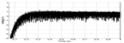
Fig.
4. Error signal (difference between Vreal and Vref ) of the
proposed FLC-based SEPIC converter.
Fig.
5. Variable-load inverter current, voltage, and voltage error signals.
Fig.6.
Inverter current, voltage, and voltage error signals with lagging power factor
load for the proposed FLC-based SEPIC and inverter system.
Fig.7.
FLC-based SEPIC’s output voltage.
Fig.
8. Comparison of the power output for the proposed FLC- and PI-based SEPIC
converters.
Fig.
9. Experimental results for Vinv and Iinv with unity power factor
load.
Fig.
10. Experimental results for Vinv and Iinv with 0.766 lagging
power factor load.
Fig.
11. Harmonic analysis of the current waveform in Fig. 19.
CONCLUSION:
An
FLC-based MPPT scheme for the SEPIC converter and inverter system for PV power
applications has been presented in this paper. A prototype SEPIC
converter-based PV inverter system has also been built in the laboratory. The
DSP board TMS320F28335 is used for real-time implementation of the proposed FLC
and MPPT control algorithms. The performance of the proposed controller has
been found better than that of the conventional PI-based converters.
Furthermore, as compared to the conventional multilevel inverter, experimental
results indicated that the proposed FLC scheme can provide a better THD level
at the inverter output. Thus, it reduces the cost of the inverter and the
associated complexity in control algorithms. Therefore, the proposed FLC-based
MPPT scheme for the SEPIC converter could be a potential candidate for
real-time PV inverter applications under variable load conditions.
REFERENCES:
[1]
K.M. Tsang andW. L. Chan, “Fast acting regenerative DC electronic load based on
a SEPIC converter,” IEEE Trans. Power Electron., vol. 27, no. 1, pp.
269–275, Jan. 2012.
[2]
S. J. Chiang, H.-J. Shieh, and M.-C. Chen, “Modeling and control of PV charger
system with SEPIC converter,” IEEE Trans. Ind. Electron., vol. 56, no.
11, pp. 4344–4353, Nov. 2009.
[3]
M. G. Umamaheswari, G. Uma, and K. M. Vijayalakshmi, “Design and implementation
of reduced-order sliding mode controller for higher-order power factor
correction converters,” IET Power Electron., vol. 4, no. 9, pp. 984–992,
Nov. 2011.
[4]
A. A. Fardoun, E. H. Ismail, A. J. Sabzali, and M. A. Al-Saffar, “New efficient
bridgeless Cuk rectifiers for PFC applications,” IEEE Trans. Power
Electron., vol. 27, no. 7, pp. 3292–3301, Jul. 2012.
[5]
M. Hongbo, L. Jih-Sheng, F. Quanyuan, Y. Wensong, Z. Cong, and Z. Zheng, “A
novel valley-fill SEPIC-derived power supply without electrolytic capacitor for
LED lighting application,” IEEE Trans. Power Electron., vol. 27,
no. 6, pp. 3057–3071, Jun. 2012.


