ABSTRACT
An active power filter implemented with a four-leg voltage-source
inverter using a predictive control scheme is presented. The use of a four-leg
voltage-source inverter allows the compensation of current harmonic components,
as well as unbalanced current generated by single-phase nonlinear loads. A
detailed yet simple mathematical model of the active power filter, including
the effect of the equivalent power system impedance, is derived and used to
design the predictive control algorithm. The compensation performance of the
proposed active power filter and the associated control scheme under steady state
and transient operating condition is demonstrated through simulations and
experimental results.
KEYWORDS
1.
Active power
filter
2.
Current
control four-leg converters,
3. Predictive control.
SOFTWARE: MATLAB/SIMULINK
BLOCK DIAGRAM:

Fig. 1. Three-phase equivalent circuit of the
proposed shunt active power filter.

CONTROL BLOCK DIAGRAM:
Fig.2.
dq-based current reference generator block diagram.
EXPECTED SIMULATION RESULTS:

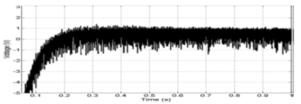
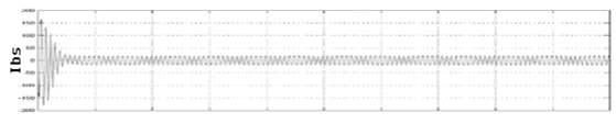
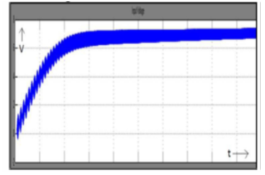
Fig.
3. Simulated waveforms of the proposed control scheme. (a) Phase to neutral
source voltage. (b) Load Current. (c) Active power filter output current. (d)
Load neutral current. (e) System neutral current. (f) System currents. (g) DC voltage
converter.


Fig. 4.
Experimental transient response after APF connection. (a) Load Current iLu ,
active power filter current iou , dc-voltage converter vdc , and
system current isu . Associated frequency spectrum. (c) Voltage and
system waveforms, vsu and isu , isv , isw . (d) Current reference
signals i∗ ou , and active power filter current
iou (tracking characteristic).

Fig. 5. Experimental results for
step load change (0.6 to 1.0 p.u.). Load Current iLu , active power
filter current iou , system current isu , and dc-voltage converter
vdc .
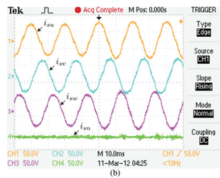

Fig. 6. Experimental
results for step unbalanced phase u load change (1.0 to 1.3 p.u.). (a) Load
Current iLu , load neutral current iLn , active power filter
neutral current ion , and system neutral current isn . (b) System
currents isu , isv , isw , and isn .
CONCLUSION:
Improved
dynamic current harmonics and a reactive power compensation scheme for power
distribution systems with generation from renewable sources has been proposed
to improve the current quality of the distribution system. Advantages of the proposed
scheme are related to its simplicity, modeling, and implementation. The use of
a predictive control algorithm for the converter current loop proved to be an
effective solution for active power filter applications, improving current
tracking capability, and transient response. Simulated and experimental results
have proved that the proposed predictive control algorithm is a good
alternative to classical linear control methods. The predictive current control
algorithm is a stable and robust solution. Simulated and experimental results
have shown thecompensation effectiveness of the proposed active power filter.
REFERENCES:
[1]
J. Rocabert, A. Luna, F. Blaabjerg, and P. Rodriguez, “Control of power converters
in AC microgrids,” IEEE Trans. Power Electron., vol. 27, no. 11, pp.
4734–4749, Nov. 2012.
[2]
M. Aredes, J. Hafner, and K. Heumann, “Three-phase four-wire shunt active
filter control strategies,” IEEE Trans. Power Electron., vol. 12, no. 2,
pp. 311–318, Mar. 1997.
[3]
S. Naidu and D. Fernandes, “Dynamic voltage restorer based on a four leg voltage
source converter,” Gener. Transm. Distrib., IET, vol. 3, no. 5, pp.
437–447, May 2009.
[4]
N. Prabhakar and M. Mishra, “Dynamic hysteresis current control to minimize
switching for three-phase four-leg VSI topology to compensate nonlinear load,” IEEE
Trans. Power Electron., vol. 25, no. 8, pp. 1935–1942, Aug. 2010.