Cascade Dual Buck
Inverter With Phase-Shift Control


ABSTRACT:
This paper presents a new type of cascade inverter based
on dual buck topology and phase-shift control scheme. The proposed cascade dual
buck inverter with phase-shift control inherits all the merits of dual buck
type inverters and overcomes some of their drawbacks. Compared to traditional
cascade inverters, it has much enhanced system reliability thanks to no
shoot-through problems and lower switching loss with the help of using power MOSFETs.
With phase-shift control, it theoretically eliminates the inherent current
zero-crossing distortion of the single-unit dual buck type inverter. In
addition, phase-shift control and cascade topology can greatly reduce the
ripple current or cut down the size of passive components by increasing the
equivalent switching frequency. A cascade dual buck inverter has been designed
and tested to demonstrate the feasibility and advantages of the system by
comparing single-unit dual buck inverter, 2-unit and 3-unit cascade dual buck
inverters at the same 1 kW, 120 V ac output conditions.
KEYWORDS:
1. Cascade inverter
2. Dual buck inverter
3. Phase-shift control.
SOFTWARE: MATLAB/SIMULINK
BLOCK DIAGRAM:
Fig. 1. Topology of cascade dual buck
half-bridge inverter.
Fig.
2. Single-unit dual buck full-bridge inverter serving as one cell for cascade dual
buck full-bridge inverter. (a)Single-unit dual buck full-bridge inverter. (b)
Cascade dual buck full-bridge inverter.
EXPECTED SIMULATION RESULTS:
Fig.
3. Output current io , ac and dc voltage waveforms for
single-unit, 2-unit cascade, and 3-unit cascade inverter system at 1 kW. (a)
Single-unit inverter. (b) 2-unit cascade inverter. (c) 3-unit cascade inverter.
Fig.
4. Output current io , ac and dc voltage waveforms for
single-unit, 2-unit cascade inverter system at 300 W. (a) Single-unit inverter.
(b) 2-unit cascade inverter.
Fig.
5. Output positive half-cycle current iP , ac and dc voltage
waveforms for single-unit, 2-unit cascade, and 3-unit cascade inverter system
at 1 kW. (a) Single-unit inverter. (b) 2-unit cascade inverter. (c) 3-unit
cascade inverter.
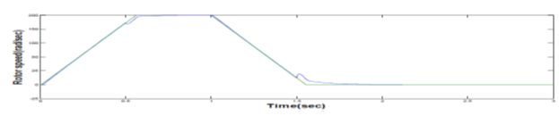
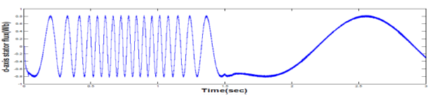
Fig.6.
Load step-up and step-down tests for single-unit inverter and 3-unit cascade
inverter system. (a) Load step up test for single-unit inverter. (b) Load step-down
test for single-unit inverter. (c) Load step-up test for 3-unit cascade inverter.
(d) Load step-down test for 3-unit cascade inverter.
CONCLUSION:
A
new series of cascade dual buck inverters has been proposed based on
single-unit dual buck inverters. The cascade dual buck inverter has all the
merits of traditional cascade inverters, and improves on its reliability by
eliminating shoot-through worries and dead-time concerns. With the adoption of
phase-shift control, the cascade dual buck inverter solves the inherent current
zero-crossing distortion problem of single-unit dual buck inverter. To prove
the effectiveness of the proposed topology and control scheme, a cascade dual
buck half-bridge inverter system operating at standalone mode with 1 kW, 120 V
ac output capability has been designed and tested. By comparison of
experimental results of single-unit dual buck inverter with 2-unit and 3-unit cascade
dual buck inverters, the viability and advantages of the cascade dual buck
inverter are validated
REFERENCES:
[1]
J. S. Lai and F. Peng, “Multilevel converters—A new breed of power converter,” IEEE
Trans. Ind. Electron., vol. 32, no. 3, pp. 509–517, May/Jun. 1996.
[2]
J. Rodriguez, J. S. Lai, and F. Peng, “Multilevel inverters: A survey of
topologies, controls, and applications,” IEEE Trans. Ind. Electron., vol.
49, no. 4, pp. 724–738, Aug. 2002.
[3]
M.Malinowski, K. Gopakumar, J. Rodriguez, andM. A. P´erez, “A survey on
cascaded multilevel inverters,” IEEE Trans. Ind. Electron., vol. 57, no.
7, pp. 2196–2206, Jul. 2010.
[4]
L. G. Franquelo, J. Rodriguez, J. I. Leon, S. Kouro, R. Portillo, and M. A. M.
Prats, “The age of multilevel converters arrives,” IEEE Ind. Electron. Mag.,
vol. 2, no. 2, pp. 28–39, Jun. 2008.
[5]
F. Z. Peng and J. S. Lai, “A multilevel voltage-source inverter with separate dc
sources for staticVAR generation,” in Proc. Conf. Rec. IEEE-IAS Annu. Meeting,
Lake Buena Vista, FL, Oct. 8–12, 1995, pp. 2541–2548.