asokatechnologies@gmail.com 09347143789/09949240245

Search This Blog

Sunday 19 April 2015

Direct torque control of squirrel cage induction motor for optimum current ripple using three-level inverter

Direct torque control of squirrel cage induction motor for optimum current ripple using three-level inverter


ABSTRACT:

Three-level neutral point clamped (NPC) inverters have been widely used in medium voltage applications. In this study, direct torque control strategy for sensorless squirrel-cage induction motor (SQIM) using NPC three-level inverter is presented. The proposed control strategy optimises the current ripple in steady state and also gives a high dynamic performance of torque in transient state. The advantage of having low dv/dt for three-level inverter output voltage is retained. The control strategy is verified on a 7.5 hp SQIM drive with three-level insulated-gate bipolar transistor (IGBT) inverter. Experimental results validate the steady state and the dynamic performance of the proposed control strategy.

 SOFTWARE: MATLAB/SIMULINK

BLOCK DIAGRAM:

 Figure 1: Three-level diode clamped inverter
                                       

Figure 2: Block diagram of the controller

EXPECTED SIMULATION RESULTS:


Figure 3: Trajectory of the stator flux in stationary α –β Plane


Figure 4: Experimentally estimated rotor flux (Ѱrsα, Ѱrsβ) at a frequency of 5 Hz


Figure 5: Three-level motor line voltage


 Figure 6: Torque reference and actual torque ripple
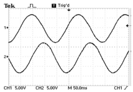


Figure 7: Steady state speed and line current waveforms (a) Experimental waveform of speed (ωe) and line current (is) at steady state (b) Zoomed waveform of line current showing the ripples


Figure 8: Experimental waveforms of speed (ωe) and line current (is) at steady state at 14 Hz
                 
Figure 9: Torque reference (m*d) and actual torque (md) during transient

CONCLUSION:

This paper has introduced a direct torque and flux control for SQIM using neutral point clamped three-level inverter. The operation of the drive is divided into two regions – low frequency operation and high-frequency operation. Separate switching strategies are proposed for these two regions of operation. The proposed strategy optimises the switching to have minimum dv/dt in the motor line voltages. It also optimises the current ripple in steady state and gives a fast torque response during transient. There is an effective reduction in the dv/dt applied to the motor terminals. This in turn reduces the bearing current and shaft voltages [14, 15] of the motor thereby increasing the life of the motor. Experimental results using SQIM and three-level inverter validate the proposed strategy.

REFERENCES:

[1] NABAE A., TAKAHASHI I., AKAGI H.: ‘A new neutral point clamped inverter’, IEEE Trans. Ind. Appl., 1981, IA-17, (5), pp. 518–523
[2] LAI J.-S., PENG F.Z.: ‘Multilevel converters – a new breed of power converters’, IEEE Trans. Ind. Appl., 1996, 32, (3), pp. 509–517
[3] MCGRATH B.P., HOLMES D.G., LIPO T.A.: ‘Optimized space vector switching sequences for multilevel inverters’, IEEE Trans. Power Electron., 2003, 18, (6), pp. 1293–1301
[4] BUJA G.S., KAZMIERKOWSKI M.P.: ‘Direct torque control of PWM inverter-fed AC motors – a survey’, IEEE Trans. Power Electron., 2004, 51, (4), pp. 744–757

[5] CASADEI D., SERRA G., TANI A., ZARRI L.: ‘Assessment of direct torque control for induction motor drives’, Bull. Pol. Acad. Sci., Techn. Sci., 2006, 54, (3), pp. 237–254

Wednesday 8 April 2015

Wind driven Induction Generator with Vienna Rectifier and PV for Hybrid Isolated Generations


Wind driven Induction Generator with Vienna Rectifier and PV for Hybrid Isolated Generations

ABSTRACT:

 Hybrid PV-wind generation shows higher availability as compared to PV or wind alone. For rural electrifications, researches are focused on hybrid power system which provides sustainable power. The variable voltage and frequency of the self excited induction generator (SEIG) is rectified through Vienna rectifier (three switches) to the required D.C voltage level and fed to common D.C bus. The variable output voltage of PV module is controlled by DC/DC converter using proposed fuzzy logic controller and fed to common D.C bus. The DC bus collects the total power from the wind and photovoltaic system and used to charge the battery as well as to supply the A.C loads through inverter. A dynamic mathematical model and MATLAB simulations for the entire scheme is presented. Results from the simulations and experimental tests bring out the suitability of the proposed hybrid scheme in remote areas.

KEYWORDS:
1. DC-DC converter
2. Fuzzy logic
3. SEIG
4. PV array
5. Vienna Rectifier
6. Wind energy.

SOFTWARE: MATLAB/SIMULINK

BLOCK DIAGRAM:


Figure 1. Schematic diagram of solar-wind hybrid scheme


EXPECTED SIMULATION RESULTS:


Figure 2: Simulated and Experimental waveforms


                                                                       Figure 3(a) Conventional Six Pulse Converter


  Figure 3(b) vienna Rectifier


                            Figure 3(c) per phase input voltage and current waveforms of  vienna Rectifier

             
CONCLUSION:
A hybrid scheme for isolated applications, employing solar and wind driven induction generator with Vienna rectifier, is proposed with fuzzy logic controller, with optimized rule-base. Hence it is very suitable for the rural electrification in remote areas where grid cannot be accessed. The photovoltaic characteristics and capacitance requirements of SEIG are discussed. Using the mathematical model described the dynamic characteristics of the hybrid scheme to maintain almost the desired load voltage is also discussed. The simulated results are focused on both the steady-state and dynamic behavior of the hybrid scheme which demonstrates the validity of the proposed model. The simulation and the experimental result of hybrid scheme shows the operation of the controller for constant load voltage had inherently resulted in balancing of power between the two sources while supplying constant power to the load.

REFERENCES:

[1] Y.Jaganmohan Reddy, Y.V. Pavan kumar, K. padma raju, and Anil kumar ramesh, “ Retrofitted Hybrid Power System Design With Renewable Energy Sources for Buildings”, IEEE Transaction on Smart Grid , Vol.3, no.4, pp. 2174-2186, Dec 2012.
[2] S.Meenakshi, K.Rajambal, C.Chellamuthu, and S.Elangovan, “Intelligent Controller for Stand-Alone Hybrid Generation System”, Power India Conference IEEE, pp 8-15, 2006.
[3] Ashraf A.Ahmed, Li Ran, Jim Bumby, “Simulation and control of a Hybrid PV-Wind System”, Power Electronics Machines & Drives, PEMD 4th IET conference, pp 421-425, 2008.
[4] Meenakshmisundaram Arutchelvi, Samuel Arul Daniel, “Grid Connected Hybrid Dispersed Power Generators Based on PV Array And Wind Driven Induction Generator”, Journal of Electrical Engineering, Vol., 60, pp 313-320, 2009.
[5] Hao Chen, Dionysios C. Aliprantis , “ Analysis of Squirrel-cage Induction Generators with Vienna Rectifier for Wind Energy Conversion System”, IEEE Transactions on Energy Conversion, Vol.26, no.3, 2011.


Tuesday 7 April 2015

Cascade Dual Buck Inverter With Phase-Shift Control

 Cascade Dual Buck Inverter With Phase-Shift Control

ABSTRACT:
                                 
This paper presents a new type of cascade inverter based on dual buck topology and phase-shift control scheme. The proposed cascade dual buck inverter with phase-shift control inherits all the merits of dual buck type inverters and overcomes some of their drawbacks. Compared to traditional cascade inverters, it has much enhanced system reliability thanks to no shoot-through problems and lower switching loss with the help of using power MOSFETs. With phase-shift control, it theoretically eliminates the inherent current zero-crossing distortion of the single-unit dual buck type inverter. In addition, phase-shift control and cascade topology can greatly reduce the ripple current or cut down the size of passive components by increasing the equivalent switching frequency. A cascade dual buck inverter has been designed and tested to demonstrate the feasibility and advantages of the system by comparing single-unit dual buck inverter, 2-unit and 3-unit cascade dual buck inverters at the same 1 kW, 120 V ac output conditions.

KEYWORDS:
1. Cascade inverter
2. Dual buck inverter
3. Phase-shift control.

SOFTWARE: MATLAB/SIMULINK


BLOCK DIAGRAM:


Fig. 1. Topology of cascade dual buck half-bridge inverter.


Fig. 2. Single-unit dual buck full-bridge inverter serving as one cell for cascade dual buck full-bridge inverter. (a)Single-unit dual buck full-bridge inverter. (b) Cascade dual buck full-bridge inverter.

EXPECTED SIMULATION RESULTS:


Fig. 3. Output current io , ac and dc voltage waveforms for single-unit, 2-unit cascade, and 3-unit cascade inverter system at 1 kW. (a) Single-unit inverter. (b) 2-unit cascade inverter. (c) 3-unit cascade inverter.


Fig. 4. Output current io , ac and dc voltage waveforms for single-unit, 2-unit cascade inverter system at 300 W. (a) Single-unit inverter. (b) 2-unit cascade inverter.


Fig. 5. Output positive half-cycle current iP , ac and dc voltage waveforms for single-unit, 2-unit cascade, and 3-unit cascade inverter system at 1 kW. (a) Single-unit inverter. (b) 2-unit cascade inverter. (c) 3-unit cascade inverter.


Fig.6. Load step-up and step-down tests for single-unit inverter and 3-unit cascade inverter system. (a) Load step up test for single-unit inverter. (b) Load step-down test for single-unit inverter. (c) Load step-up test for 3-unit cascade inverter. (d) Load step-down test for 3-unit cascade inverter.

CONCLUSION:
A new series of cascade dual buck inverters has been proposed based on single-unit dual buck inverters. The cascade dual buck inverter has all the merits of traditional cascade inverters, and improves on its reliability by eliminating shoot-through worries and dead-time concerns. With the adoption of phase-shift control, the cascade dual buck inverter solves the inherent current zero-crossing distortion problem of single-unit dual buck inverter. To prove the effectiveness of the proposed topology and control scheme, a cascade dual buck half-bridge inverter system operating at standalone mode with 1 kW, 120 V ac output capability has been designed and tested. By comparison of experimental results of single-unit dual buck inverter with 2-unit and 3-unit cascade dual buck inverters, the viability and advantages of the cascade dual buck inverter are validated

REFERENCES:
[1] J. S. Lai and F. Peng, “Multilevel converters—A new breed of power converter,” IEEE Trans. Ind. Electron., vol. 32, no. 3, pp. 509–517, May/Jun. 1996.
[2] J. Rodriguez, J. S. Lai, and F. Peng, “Multilevel inverters: A survey of topologies, controls, and applications,” IEEE Trans. Ind. Electron., vol. 49, no. 4, pp. 724–738, Aug. 2002.
[3] M.Malinowski, K. Gopakumar, J. Rodriguez, andM. A. P´erez, “A survey on cascaded multilevel inverters,” IEEE Trans. Ind. Electron., vol. 57, no. 7, pp. 2196–2206, Jul. 2010.
[4] L. G. Franquelo, J. Rodriguez, J. I. Leon, S. Kouro, R. Portillo, and M. A. M. Prats, “The age of multilevel converters arrives,” IEEE Ind. Electron. Mag., vol. 2, no. 2, pp. 28–39, Jun. 2008.
[5] F. Z. Peng and J. S. Lai, “A multilevel voltage-source inverter with separate dc sources for staticVAR generation,” in Proc. Conf. Rec. IEEE-IAS Annu. Meeting, Lake Buena Vista, FL, Oct. 8–12, 1995, pp. 2541–2548.

Thursday 2 April 2015

Mitigation of Harmonics by Hysteresis Control Technique of VSI Based Statcom

Mitigation of Harmonics by Hysteresis Control
Technique of VSI Based Statcom
ABSTRACT:

Modern industrial equipments are more sensitive to these power quality problems than before and need higher quality of electrical power. Power electronic based power processing offers higher efficiency, compact size and better controllability. But on the flip side, due to switching actions, these systems behave as non-linear loads. This creates power quality problems such as voltages Sag/Swell, flickers; harmonics, asymmetric of voltage have become increasingly serious. At the same time, modern industrial equipments are more sensitive to these power quality problems than before and need higher quality of electrical power. This paper mainly deals with shunt active power filter which has been widely used for harmonic elimination. Active power filter which has been used here monitors the load current constantly and continuously adapt to the changes in load harmonics. The performance of three phase shunt active power filter using three phase two phase transformation with PI and Hysteresis current controller is explained in this paper.

KEYWORDS:
1.  Power filters (APF)
2. Composite load
3. Harmonic compensation
4. Linear and non linear load
5. Reactive power
6. Power Quality
7. Harmonics
8. Voltage Source Inverter.

SOFTWARE: MATLAB/SIMULINK

BLOCK DIAGRAM:      


Figure 1. Principle of operation of an APF compensating a diode rectifier
Figure 2. Basic Compensation Technique
EXPECTED SIMULATION RESULTS:
             

                                                                                                                                                        Time(secs)
Figure 3.1. Supply voltage waveform

                                                                                                                                                       Time(secs) 
Figure 3.2.a  Load Voltage

                                                                                                                                                               Time (secs)
Figure 3.2.b   Load Current


                                                                                                                                                                                  Time (secs)
                                                      Figure 3.3. source current before and after control for each phase


                                                                                                                   Time (secs)
                           Figure 3.4 source current before and after control for all the three phases.                                                           


                                   Figure 3.5 Injected current before and after control for each phase.                        Time (secs)


                                                                                                                                                                   Time (secs)
                                          Figure 3.6 Injected current before and after control for all the three phases.


CONCLUSION:
An extensive review of AF’s has been presented to provide a clear perspective on various aspects of the AF to the researchers and engineers working in this field. The substantial increase in the use of solid-state power control results in harmonic pollution above the tolerable limits. The utilities in the long run will induce the consumers with nonlinear loads to use the AF’s for maintaining the power quality at acceptable levels. A large number of AF configurations are available to compensate harmonic current, reactive power, neutral current, unbalance current, and harmonics. The consumer can select the AF with the required features. Static compensation (STATCOM) gets more popular as the flexible AC transmission (FACTS) devices increase. The transformer-less STATCOM has low cost and concentrates the research interests; however, the capacitors voltage unbalance problem will deteriorate its performance with more harmonics and over current/voltage faults. A very simple hysteresis current controller based control technique with help of instantaneous power theory is proposed for STATCOM. A MATLAB/Simulink based model has been simulated. Simulation result shows the input current harmonics produce by nonlinear load is reduced after using the control strategy. FFT analysis shows the reduction in THD is remarkable.

REFERENCES:       
[1] Understanding FACTS: Concepts and Technology of Flexible AC Transmission Systems. Narain G. Hingorani, Laszlo Gyugyi. Wiley IEEE press.

[2] “A Few Aspects of Power Quality Improvement Using Shunt Active Power Filter” -C.Nalini Kiran, Subhransu Sekhar Dash, S.Prema Latha. International Journal of Scientific & Engineering Research Volume 2, Issue 5, May-2011, ISSN 2229-5518

Grid Interconnection of Renewable Energy Sources at the Distribution Level With Power-Quality Improvement Features

Grid Interconnection of Renewable Energy Sources at the Distribution Level With Power-Quality Improvement Features

ABSTRACT:

Renewable energy resources (RES) are being increasingly connected in distribution systems utilizing power electronic converters. This paper presents a novel control strategy for achieving maximum benefits from these grid-interfacing inverters when installed in 3-phase 4-wire distribution systems. The inverter is controlled to perform as a multi-function device by incorporating active power filter functionality. The inverter can thus be utilized as: 1) power converter to inject power generated from RES to the grid, and 2) shunt APF to compensate current unbalance, load current harmonics, load reactive power demand and load neutral current. All of these functions may be accomplished either individually or simultaneously. With such a control, the combination of grid-interfacing inverter and the 3-phase 4-wire linear/non-linear unbalanced load at point of common coupling appears as balanced linear load to the grid. This new control concept is demonstrated with extensive MATLAB/Simulink simulation studies and validated through digital signal processor-based laboratory experimental results.

KEYWORDS:

1.      Active power filter (APF)
2.      Distributed generation (DG)
3.       Distribution system
4.       Grid interconnection
5.       Power quality (PQ)
6.       Renewable energy.

SOFTWARE: MATLAB/SIMULINK

BLOCK DIAGRAM:


Fig. 1. Schematic of proposed renewable based distributed generation system.


EXPECTED SIMULATION RESULTS:


Fig. 2. Simulation results: (a) Grid voltages, (b) Grid Currents (c) Unbalancedload currents, (d) Inverter Currents.


Fig. 3. Simulation results: (a) PQ-Grid, (b) PQ-Load, (c) PQ-Inverter, (d) dc-link voltage.


CONCLUSION:
This paper has presented a novel control of an existing grid interfacing inverter to improve the quality of power at PCC for a 3-phase 4-wireDGsystem. It has been shown that the grid interfacing inverter can be effectively utilized for power conditioning without affecting its normal operation of real power transfer. The grid-interfacing inverter with the proposed approach can be utilized to:
i) Inject real power generated from RES to the grid, and/or,
ii) Operate as a shunt Active Power Filter (APF).
This approach thus eliminates the need for additional power conditioning equipment to improve the quality of power at PCC. Extensive MATLAB/Simulink simulation as well as the DSP based experimental results have validated the proposed approach and have shown that the grid-interfacing inverter can be utilized as a multi-function device. It is further demonstrated that the PQ enhancement can be achieved under three different scenarios: 1) PRES = 0 , 2)PRES < PLOAD , and  3)PRES > PLOAD . The current unbalance, current harmonics and load reactive power, due to unbalanced and non-linear load connected to the PCC, are compensated effectively such that the grid side currents are always maintained as balanced and sinusoidal at unity power factor. Moreover, the load neutral current is prevented from flowing into the grid side by compensating it locally from the fourth leg of inverter. When the power generated from RES is more than the total load power demand, the grid-interfacing inverter with the proposed control approach not only fulfills the total load active and reactive power demand (with harmonic compensation) but also delivers the excess generated sinusoidal active power to the grid at unity power factor.


REFERENCES:
[1] J. M. Guerrero, L. G. de Vicuna, J. Matas, M. Castilla, and J. Miret, “A wireless controller to enhance dynamic performance of parallel inverters in distributed generation systems,” IEEE Trans. Power Electron., vol. 19, no. 5, pp. 1205–1213, Sep. 2004.
[2] J. H. R. Enslin and P. J. M. Heskes, “Harmonic interaction between a large number of distributed power inverters and the distribution network,” IEEE Trans. Power Electron., vol. 19, no. 6, pp. 1586–1593, Nov. 2004.
[3] U. Borup, F. Blaabjerg, and P. N. Enjeti, “Sharing of nonlinear load in parallel-connected three-phase converters,” IEEE Trans. Ind. Appl., vol. 37, no. 6, pp. 1817–1823, Nov./Dec. 2001.
[4] P. Jintakosonwit, H. Fujita, H. Akagi, and S. Ogasawara, “Implementation and performance of cooperative control of shunt active filters for harmonic damping throughout a power distribution system,” IEEE Trans. Ind. Appl., vol. 39, no. 2, pp. 556–564, Mar./Apr. 2003.
[5] J. P. Pinto, R. Pregitzer, L. F. C. Monteiro, and J. L. Afonso, “3-phase 4-wire shunt active power filter with renewable energy interface,” presented at the Conf. IEEE Renewable Energy & Power Quality, Seville, Spain, 2007.