asokatechnologies@gmail.com 09347143789/09949240245

Search This Blog

Sunday 10 July 2016

A New Control Strategy for Active and Reactive Power Control of Three-Level VSC Based HVDC System


ABSTRACT

This paper presents a new control strategy for real and reactive power control of three-level multipulse voltage source converter based High Voltage DC (HVDC) transmission system operating at Fundamental Frequency Switching (FFS). A three-level voltage source converter replaces the conventional two-level VSC and it is designed for the real and reactive power control is all four quadrants operation. A new control method is developed for achieving the reactive power control by varying the pulse width and by keeping the dc link voltage constant. The steady state and dynamic performances of HVDC system interconnecting two different frequencies network are demonstrated for active and reactive powers control. Total numbers of transformers used in the system are reduced in comparison to two level VSCs. The performance of the HVDC system is also improved in terms of reduced harmonics level even at fundamental frequency switching.

KEYWORDS

1.      HVDC
2.      Voltage Source Converter
3.      Multilevel
4.      Multipulse
5.      Dead Angle (β)

SOFTWARE:  MATLAB/SIMULINK

BLOCK DIAGRAM:


Fig. 1 A three-level 24-Pulse voltage source converter based HVDC system


CONTROL SCHEME


Fig. 2 Control scheme of three-level VSC based HVDC system using dynamic dead angle (β) Control

EXPECTED SIMULATION RESULTS


Fig. 3 Performance of rectifier station during simultaneous real and reactive power control of three-level 24-pulse VSC based HVDC system


Fig. 4 Performance of inverter station during simultaneous real and reactive power control of three-level 24-pulse VSC based HVDC system


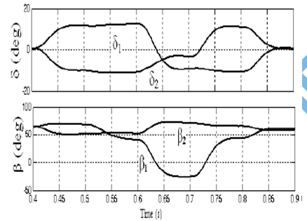
Fig. 5 Variation of angles (δ) and (β) values of three-level 24-pulse VSC based HVDC system during simultaneous real and reactive power control

CONCLUSION

A new control method for three-level 24-pulse voltage source converter configuration has been designed for HVDC system. The performance of this 24-pulse VSC based HVDC system using the control method has been demonstrated in active power control in bidirectional, independent control of the reactive power and power quality improvement. A new dynamic dead angle (β) control has been introduced for three-level voltage source converter operating at fundamental frequency switching. In this control the HVDC system operation is successfully demonstrated and also an analysis of (β) value for various reactive power requirement and harmonic performance has been carried out in detail. Therefore, the selection of converter operation region is more flexible according to the requirement of the reactive power and power quality.

REFERENCES

[1] Gunnar Asplund, Kjell Eriksson and kjell Svensson, “DC Transmission based on Voltage Source Converters,” in Proc. Of CIGRE SC14 Colloquium in South Africa 1997, pp.1-7.
[2] “HVDC Light DC Transmission based on Voltage Source Converter,” ABB Review Manual 1998, pp. 4-9.
[3] Xiao Wang and Boon-Tech Ooi, “High Voltage Direct Current Transmission System Based on Voltage Source Converter,” in IEEEPESC’ 90 Record, vol.1, pp.325-332.
[4] Michael P. Bahrman, Jan G. Johansson and Bo A. Nilsson, “Voltage Source Converter Transmission Technologies-The Right Fit for the Applications,” in Proc. of IEEE-PES General Meeting, Toronto, Canada, July-2003, pp.1840-1847.

[5] Y. H. Liu R. H. Zhang, J. Arrillaga and N. R. Watson, “An Overview of Self-Commutating Converters and their Application in Transmission and Distribution,” in Conf. Proc of IEEE/PES T & DConf. & Exhibition, Asia and Pacific Dalian, China 2005, pp.1-7.

Friday 8 July 2016

Analysis and Design of Three-Level, 24-Pulse Double Bridge Voltage Source Converter Based HVDC System for Active and Reactive Power Control


ABSTRACT
This paper deals with the analysis, design and control of a three-level 24-pulse Voltage Source Converter (VSC) based High Voltage Direct Current (HVDC) system. A three level VSC operating at fundamental frequency switching (FFS) is proposed with 24-pulse VSC structure to improve the power quality and reduce the converter switching losses for high power applications. The design of three-level VSC converter and system parameters such as ac inductor and dc capacitor is presented for the proposed VSC based HVDC system. It consists of two converter stations fed from two different ac systems. The active power is transferred between the stations either way. The reactive power is independently controlled in each converter station. The three-level VSC is operated at optimized dead angle (β). A coordinated control algorithm for both the rectifier and an inverter stations for bidirectional active power flow is developed based on FFS and local reactive power generation. This results in a substantial reduction in switching losses and avoiding the reactive power plant. Simulation is carried to verify the performance of the proposed control algorithm of the VSC based HVDC system for bidirectional active power flow and their independent reactive power control.

KEYWORDS
Voltage Source Converter (VSC), Three-level VSC, Fundamental Frequency Switching (FFS), HVDC System, Power Flow Control, Reactive Power Control, Power Quality, Total Harmonic Distortion (THD), Dead Angle (β).

SOFTWARE: MATLAB/SIMULINK

BLOCK DIAGRAM:
Fig. 1 Three-level 24-pulse double bridge VSC based HVDC system

EXPECTED SIMULATION RESULTS:

Fig. 2a Performance of rectifier station during reactive power control of three level 24-pulse VSC HVDC system
Fig. 2b Performance of Inverter station during reactive power control at rectifier station of three-level 24 pulse VSC HVDC system
Fig. 2c Variation of (δ) and (α) values for rectifier and inverter Stations for reactive power variation of a three-level 24-pulse VSC HVDC system
Fig. 3a Rectifier station during active power reversal of three-level 24-pulse VSC HVDC system
Fig. 3b Inverter station during active power reversal of three-level 24-pulse VSC HVDC system
Fig. 3c Variation of (δ) and (α) values during active power reversal of three level 24-pulse VSC HVDC system.


CONCLUSION
A new three-level, 24-pulse voltage source converter based HVDC system operating at fundamental frequency switching has been designed and its model has been developed and it is successfully tested for the independent control of active and reactive powers and acceptable level harmonic requirements. The reactive power has been controlled independent of the active power at both conditions. The converter has been successfully operated in all four quadrants of active and reactive powers with the proposed control. The reversal of the active power flow has been implemented by reversing the direction of dc current without changing the polarity of dc voltage which is very difficult in conventional HVDC systems. The power quality of the HVDC system has also improved with three-level 24-pulse converter operation. The harmonic performance of this three-level, 24-pulse VSC has been observed to an equivalent to two-level 48-pulse voltage source converter.

REFERENCES
 [1] “It’s time to connect,” Technical description of HVDC Light Technology, ABB HVDC Library.
[2] J. Arrillaga, “High Voltage Direct Current Transmission,” 2nd Edition, IEE Power and Energy Series 29, London, 1998.
[3] Vijay K. Sood, “HVDC and FACTS Controllers - Applications of Static Converters in Power Systems,” Kluwer Academic Publishers, Masachusetts, 2004.
[4] J. Arrillaga, Y. H. Liu and N. R. Waston, “Flexible Power Transmission- The HVDC Options,” John Wiley & Sons, Ltd, Chichester, UK, 2007.

[5] J. Arrillaga and M. E. Villablanca, “A modified parallel HVDC convertor for 24 pulse operation,” IEEE Trans. on Power Delivery, vol. 6, no. 1, pp. 231-237, Jan 1991.


Thursday 30 June 2016

A Novel Control Method for Transformerless H-Bridge Cascaded STATCOM with Star Configuration


ABSTRACT
This paper presents a transformerless static synchronous compensator (STATCOM) system based on multilevel H-bridge converter with star configuration. This proposed control methods devote themselves not only to the current loop control but also to the dc capacitor voltage control. With regards to the current loop control, a nonlinear controller based on the passivity-based control (PBC) theory is used in this cascaded structure STATCOM for the first time. As to the dc capacitor voltage control, overall voltage control is realized by adopting a proportional resonant controller. Clustered balancing control is obtained by using an active disturbances rejection controller. Individual balancing control is achieved by shifting the modulation wave vertically which can be easily implemented in a field-programmable gate array. Two actual H-bridge cascaded STATCOMs rated at 10 kV 2 MVA are constructed and a series of verification tests are executed. The experimental results prove that H-bridge cascaded STATCOM with the proposed control methods has excellent dynamic performance and strong robustness. The dc capacitor voltage can be maintained at the given value effectively.

KEYWORDS:
Active disturbances rejection controller (ADRC), H-bridge cascaded, passivity-based control (PBC), proportional resonant (PR) controller, shifting modulation wave, static synchronous compensator (STATCOM).

SOFTWARE: MATLAB/SIMULINK

CONTROL BLOCK DIAGRAM:

Fig. 1. Control block diagram for the 10 kV 2 MVA H-bridge cascaded STATCOM.


Fig. 2. Block diagram of PBC.

EXPERIMENTAL RESULTS:


Fig. 3. Experimental results verify the effect of PBC in steady-state process. (a) Ch1: reactive current; Ch2: compensating current; Ch3: residual current of grid. (b) Ch1: reactive current; Ch2: compensating current; Ch3: residual current of grid.


Fig. 4. Experimental results show the dynamic performance of STATCOM in the dynamic process. Ch1: reactive current; Ch2: compensating current; Ch3: residual current of grid.


Fig. 5. Experimental results in the startup process and stopping process. (a) Ch1: reactive current; Ch2: compensating current; Ch3: residual current of grid. (b) Ch1: reactive current; Ch2: compensating current; Ch3: residual current of grid.

CONCLUSION

This paper has analyzed the fundamentals of STATCOM based on multilevel H-bridge converter with star configuration. And then, the actual H-bridge cascaded STATCOM rated at 10 kV 2 MVA is constructed and the novel control methods are also proposed in detail. The proposed method has the following characteristics.
1) A PBC theory-based nonlinear controller is first used in STATCOM with this cascaded structure for the current loop control, and the viability is verified by the experimental results.
2) The PR controller is designed for overall voltage control and the experimental result proves that it has better performance in terms of response time and damping profile compared with the PI controller.
3) The ADRC is first used in H-bridge cascaded STATCOM for clustered balancing control and the experimental results verify that it can realize excellent dynamic compensation for the outside disturbance.
4) The individual balancing control method which is realized by shifting the modulation wave vertically can be easily implemented in the FPGA.
The experimental results have confirmed that the proposed methods are feasible and effective. In addition, the findings of this study can be extended to the control of any multilevel voltage source converter, especially those with H-bridge cascaded structure.

REFERENCES

[1] B. Gultekin and M. Ermis, “Cascaded multilevel converter-based transmission STATCOM: System design methodology and development of a 12 kV ±12 MVAr power stage,” IEEE Trans. Power Electron., vol. 28, no. 11, pp. 4930–4950, Nov. 2013.
[2] B. Gultekin, C. O. Gerc¸ek, T. Atalik, M. Deniz, N. Bic¸er, M. Ermis, K. Kose, C. Ermis, E. Koc¸, I. C¸ adirci, A. Ac¸ik, Y. Akkaya, H. Toygar, and S. Bideci, “Design and implementation of a 154-kV±50-Mvar transmission STATCOM based on 21-level cascaded multilevel converter,” IEEE Trans. Ind. Appl., vol. 48, no. 3, pp. 1030–1045, May/Jun. 2012.
[3] S. Kouro, M. Malinowski, K. Gopakumar, L. G. Franquelo, J. Pou, J. Rodriguez, B.Wu,M. A. Perez, and J. I. Leon, “Recent advances and industrial applications of multilevel converters,” IEEE Trans. Ind. Electron., vol. 57, no. 8, pp. 2553–2580, Aug. 2010.
[4] F. Z. Peng, J.-S. Lai, J. W. McKeever, and J. VanCoevering, “A multilevel voltage-source inverter with separateDCsources for static var generation,” IEEE Trans. Ind. Appl., vol. 32, no. 5, pp. 1130–1138, Sep./Oct. 1996.
[5] Y. S. Lai and F. S. Shyu, “Topology for hybrid multilevel inverter,” Proc. Inst. Elect. Eng.—Elect. Power Appl., vol. 149, no. 6, pp. 449–458, Nov. 2002.


A Novel High Step-up DC/DC Converter Based on Integrating Coupled Inductor and Switched-Capacitor Techniques for Renewable Energy Applications


ABSTRACT
In this paper, a novel high step-up dc/dc converter is presented for renewable energy applications. The suggested structure consists of a coupled inductor and two voltage multiplier cells, in order to obtain high step-up voltage gain. In addition, two capacitors are charged during the switch-off period, using the energy stored in the coupled inductor which increases the voltage transfer gain. The energy stored in the leakage inductance is recycled with the use of a passive clamp circuit. The voltage stress on the main power switch is also reduced in the proposed topology. Therefore, a main power switch with low resistance RDS(ON) can be used to reduce the conduction losses. The operation principle and the steady-state analyses are discussed thoroughly. To verify the performance of the presented converter, a 300-W laboratory prototype circuit is implemented. The results validate the theoretical analyses and the practicability of the presented high step-up converter.

KEYWORDS:
Coupled inductor, DC/DC converters, High step-up, Switched capacitor.

SOFTWARE: MATLAB/SIMULINK

 CIRCUIT DIAGRAM:

Fig. 1. Circuit configuration of the presented high-step-up converter.

EXPERIMENTAL RESULTS:


Fig. 2. Experimental results under load 300 W.

CONCLUSION

This paper presents a new high-step-up dc/dc converter for renewable energy applications. The suggested converter is suitable for DG systems based on renewable energy sources, which require high-step-up voltage transfer gain. The energy stored in the leakage inductance is recycled to improve the performance of the presented converter. Furthermore, voltage stress on the main power switch is reduced. Therefore, a switch with a low on-state resistance can be chosen. The steady-state operation of the converter has been analyzed in detail. Also, the boundary condition has been obtained. Finally, a hardware prototype is implemented which converts the 40-V input voltage into 400-V output voltage. The results prove the feasibility of the presented converter.

REFERENCES

 [1] F.Nejabatkhah, S. Danyali, S. Hosseini, M. Sabahi, and S. Niapour, “Modeling and control of a new three-input DC–DC boost converter for hybrid PV/FC/battery power system,” IEEE Trans. Power Electron., vol. 27, no. 5, pp. 2309–2324, May 2012.
[2] R. J. Wai and K. H. Jheng, “High-efficiency single-input multiple-output DC–DC converter,” IEEE Trans. Power Electron., vol. 28, no. 2, pp. 886–898, Feb. 2013.
[3] Y. Zhao, X. Xiang, C. Li, Y. Gu, W. Li, and X. He, “Single-phase high step-up converter with improved multiplier cell suitable for half- bridgebased PV inverter system,” IEEE Trans. Power Electron., vol. 29, no. 6, pp. 2807–2816, Jun. 2014.
[4] J.H. Lee, T. J. Liang, and J. F. Chen, “Isolated coupled-inductor-integrated DC–DC converter with non-dissipative snubber for solar energy applications,” IEEE Trans. Ind. Electron., vol. 61, no. 7, pp. 3337–3348, Jul.2014.

[5] C.Olalla, C. Delineand, andD.Maksimovic, “Performance of mismatched PV systems withsubmodule integrated converters,” IEEE J. Photovoltaic, vol. 4, no. 1, pp. 396–404, Jan. 2014.

Wednesday 29 June 2016

A Multi-Input Bridgeless Resonant AC-DC Converter for Electromagnetic Energy Harvesting


ABSTRACT
Flapping electromagnetic-reed generators are investigated to harvest wind energy, even at low cut-off wind speeds. Power electronic interfaces are intended to address ac-dc conversion and power conditioning for single- or multiple-channel systems. However, the generated voltage of each generator reed at low wind speed is usually below the threshold voltage of power electronic semiconductor devices, increasing the difficulty and inefficiency of rectification, particularly at relatively low output powers. This manuscript proposes a multi-input bridgeless resonant ac-dc converter to achieve ac-dc conversion, step up voltage and match optimal impedance for a multi-channel electromagnetic energy harvesting system. Alternating voltage of each generator is stepped up through the switching LC network and then rectified by a freewheeling diode. Its resonant operation enhances efficiency and enables miniaturization through high frequency switching. The optimal electrical impedance can be adjusted through resonance impedance matching and pulse-frequency-modulation (PFM) control. A 5-cm×3-cm, six-input standalone prototype is fabricated to address power conditioning for a six-channel BreezBee wind panel.

KEYWORDS:
AC-DC conversion, electromagnetic energy harvesting, multi-input converter, resonant converter, wind energy.

SOFTWARE: MATLAB/SIMULINK

 BLOCK DIAGRAM:

Fig. 1. Multi-channel EMR generators and PEI system: (a) conventional PEI; and (b) proposed multi-input PEI.

CIRCUIT DIAGRAM:
Fig. 2. Illustrative scheme of the proposed multi-input converter (v(i)emf: EMF of #i reed; r(i)EMR: coil resistance; L(i)EMR: self-inductance; i(i)EMR: reed terminal current; v(i)EMR: reed terminal voltage; C(i)r1= C(i)r2: resonant capacitors; Lr: resonant inductor; Q(i)r1, Q(i)r2: MOSFETs; Dr: output diode; Co: output capacitor).

EXPERIMENTAL RESULTS:

      
                                       (a)                                                                         (b)
Fig. 3. Experimental waveforms of power amplifiers: fin = 20 Hz; X-axis: 10 ms/div; Y-axis: (a) vemf = 3 Vrms; Ch1 = output voltage (Vo), 2.5 V/div; Ch2 = terminal voltage (vEMR) of reed #1, 10 V/div; Ch3 = input current (iEMR) of six reeds, 50 mA/div; and (b) vemf = 0.5 Vrms; Ch1 = output voltage (Vo), 0.5 V/div; Ch2 = terminal voltage (vEMR) of reed #1, 5 V/div; Ch3 = sum of the input currents (iEMR) of six reeds, 10 mA/div.

                (a)                                                                           (b)
Fig. 4. Experimental waveforms of power amplifiers with step change: X-axis: 40 ms/div; Y-axis: (a) vemf = from 1 Vrms to 2 Vrms; Ch1 = output voltage (Vo), 1 V/div; Ch2 = terminal voltage (vEMR) of reed #1, 5 V/div; Ch3 = input current (iEMR) of six reeds, 50 mA/div; and (b) fin = from 20 Hz to 50 Hz; Ch1 = output voltage (Vo), 0.5 V/div; Ch2 = terminal voltage (vEMR) of reed #1, 5 V/div; Ch3 = input current (iEMR) of six reeds, 50 mA/div.


Fig. 5. Experimental waveforms of EMR generators: X-axis: (a) 20 ms/div; (b) 100 ms/div; Y-axis: (a) constant wind speed; (b) wind speed step change; Ch1 = terminal voltage (vEMR) of reed #2, 5 V/div; Ch2 = output voltage (Vo), 1 V/div; Ch3 = terminal voltage (vEMR) of reed #1, 10 V/div; Ch4 = input current (iEMR) of reed #1, 10 mA/div.

CONCLUSION
This manuscript introduces a multi-input bridgeless resonant ac-dc converter suitable for efficient, low-voltage, low-power, ac-dc power conversion of multiple electromagnetic generators. The multi-input single-stage topology is capable of directly converting independent, low-amplitude, alternative voltages of EMR inductive generators to a stepped-up dc output voltage with relatively high efficiency. Low-frequency alternating voltages of EMR generators are first converted into a high-frequency alternating voltage through an LC network and then rectified into a dc output voltage through a soft-switched diode. Optimal electrical impedance matching is achieved through proper LC network design and PFM control to scavenge maximum power of EMR generators. In addition, high-frequency soft-switching increases the potential of size miniaturization without suffering from switching losses. The converter performance is verified through a 5cm×3cm standalone prototype, which converts ac voltages of six-channel generators into a dc output voltage. A maximum PEI conversion efficiency of 86.3% is measured at 27-mW ac-dc power conversion. The topological concept, presented in this manuscript, can be adapted for rectification of any inductive voltage sources or electromagnetic energy-harvesting device.
REFERENCES
[1] A. Khaligh, P. Zeng, and C. Zheng, “Kinetic energy harvesting using piezoelectric and electromagnetic technologies - state of the art,” IEEE Trans. on Industrial Electronics, vol. 57, no. 3, pp. 850-860, Mar. 2010.
[2] Altenera Technology Inc., accessible online at http://altenera.com/products/.
[3] H. Jung, S. Lee, and D. Jang, “Feasibility study on a new energy harvesting electromagnetic device using aerodynamic instability,” IEEE Trans. on Magnetics, vol. 45, no. 10, pp. 4376-4379, Oct. 2009.
[4] A. Bansal, D. A. Howey, and A. S. Holmes, “CM-scale air turbine and generator for energy harvesting from low-speed flows,” in Proc. Solid-State Sensors, Actuators and Microsystems Conf., Jun. 2009, pp. 529-532.
[5] D. Rancourt, A. Tabesh, and L. G. Fréchette, “Evaluation of centimeter-scale micro windmills: aerodynamics and electromagnetic power generation,” in Proc. PowerMEMS, 2007, pp. 93-96.