asokatechnologies@gmail.com 09347143789/09949240245

Search This Blog

Saturday 3 September 2016

Advanced Hybrid System for Solar Car

Abstract

A three-input hybrid system for solar car is designed in this project. It consists of one unidirectional input power port and two bidirectional power ports with a storage element. Depending on utilization state of the battery, three different power operation modes are defined for the converter. Battery charging in the system is carried out from the amorphous solar panel mounted on the body and a solar energy harvesting charging station. Since the solar energy is directly given to the DC load, the efficiency of the system will improve. The capacitor which is connected to the lead acid battery will charge at off peak hours and discharge during the acceleration time of the car. In this proposed system energy wasted in the brakes are also recovered and used to charge the lead acid battery. Hence competent Hybrid Electric Vehicle was developed by using super capacitor and regenerative braking scheme.

Keywords

1.      PhotovoItaic array
2.       Super capacitor                         
3.      Regenerative braking
4.       DC-DC Converter

Software: MATLAB/SIMULINK


Block Diagram:


Figure 1: When the vehicle is moving on a plane


Figure 2: When the vehicle is ascending through the slope


Figure 3: When the vehicle is descending through the slope

Expected Simulation Results:


Figure 4: Output voltage of solar cell


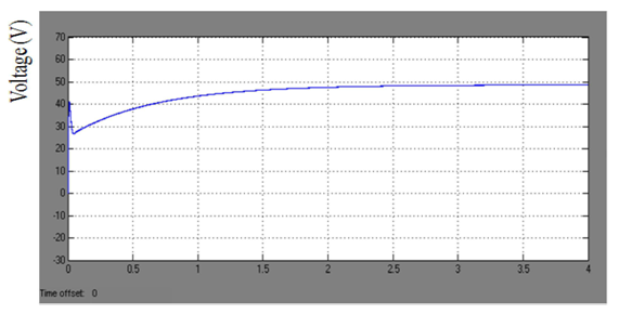
Figure 5: Output voltage of Boost converter


Figure 6: Voltage across super capacitor

Figure 7: armature current
Figure 8: Speed of Armature

Figure 9: input current to the motor


Figure 10: Discharging current from the super capacitor

Figure 11: speed of Armature

Figure 12: generated current

Conclusion

At current levels of technology, installing a super capacitor with regenerative braking scheme provides a feasible method to improve the performances of the vehicles. The simulation results of the proposed systems show that the performance of the vehicle was improved in the following aspects.
(1) Provide better working conditions for the battery and increase its operating life.
(2) Source of energy extended up to the, regenerative braking scheme along with solar source, will increase the system reliability.
(3) Since the super capacitors have the ability to provide a large current in short time acceleration, performance of the vehicle will improve. Future scope of this work is to realize hardware model of the system.

References

[I] Bin Wu, Fang Zhuo, Fei Long, WeiweiGu, Yang Qing, YanQinLiu"A management strategy for solar panel battery -super capacitor hybrid energy system in solar car" 8th International Conference on Power Electronics - ECCE Asia May 30-June 3, 2011
[2] HyunjaeYoo; Seung-Ki SuI; Yongho Park; JongchanJeong; , "System Integration and Power-Flow Management for a Series Hybrid Electric Vehicle Using Super capacitors and Batteries," Industry Applications, IEEE Transactions on , vo1.44, no.l, pp.I08-114, Jan.-Feb. 2008
[3] Jinrui N, Zhifu W', Qinglian "Simulation and Analysis of Performance of a Pure Electric Vehicle with a Super-capacitor"2006 IEEE.
[4] T. Smith, 1. Mars, and G. Turner, "Using super capacitors to improve battery performance," in Proc. IEEE Conf.PESC02, Jun., vol. 1, pp. 124-128.

[5] R. Schupbach, 1. C. Balda, "The role of Ultracapcitors in an Energy Storage Unit for Vehicle Power Management", IEEE Proceedings of the 58th Vehicular Technology Conference, VTC 2003-Fall, Vol.3, 6-9 October 2003, Orlando,Florida.

Thursday 1 September 2016

Paper Writing and Paper Publication

The scientific manuscript is a clear written document that illustrates a question and then gives a logical answer to this question based on theoretical or experimental or simulation results. A manuscript conveys the technical information to the reader, thus the presentation and discussion should be straightforward.
We do write research papers and also publish papers in good International Journals.

Asoka Technologies

Tuesday 2 August 2016

An Integrated Hybrid Power Supply for Distributed Generation Applications Fed by Nonconventional Energy Sources

ABSTRACT
A new, hybrid integrated topology, fed by photovoltaic (PV) and fuel cell (FC) sources and suitable for distributed generation applications, is proposed. It works as an uninterruptible power source that is able to feed a certain minimum amount of power into the grid under all conditions. PV is used as the primary source of power operating near maximum power point (MPP), with the FC section (block), acting as a current source, feeding only the deficit power. The unique “integrated” approach obviates the need for dedicated communication between the two sources for coordination and eliminates the use of a separate, conventional dc/dc boost converter stage required for PV power processing, resulting in a reduction of the number of devices, components, and sensors. Presence of the FC source in parallel (with the PV source) improves the quality of power fed into the grid by minimizing the voltage dips in the PV output. Another desirable feature is that even a small amount of PV power (e.g., during low insolation), can be fed into the grid. On the other hand, excess power is diverted for auxiliary functions like electrolysis, resulting in an optimal use of the energy sources. The other advantages of the proposed system include low cost, compact structure, and high reliability, which render the system suitable for modular assemblies and “plug-n-play” type applications. All the analytical, simulation results of this research are presented.

INDEX TERMS: Buck-boost, distributed generation, fuel cell, grid-connected, hybrid, maximum power point tracking (MPPT), photovoltaic.

SOFTWARE: MATLAB/SIMULINK

BLOCK DIAGRAM

Fig. 1. Various HDGS configurations. (a) Conventional, multistage topology using two H-bridge inverters [4], [6]. (b) Modified topology with only one H-bridge inverter [4]. (c) Proposed topology. λ denotes solar insolation (Suns).


SIMULATION RESULTS

Fig. 2. Simulation results of the integrated hybrid configuration showing transition from mode III to mode II and then to mode I. T1 and T2 denote the transition between mode III to mode II and mode II to mode I respectively.

Fig. 3. Simulation results of the integrated hybrid configuration operating in electrolysis mode (mode I to mode III and then to mode I). T1 and T2 denote the transition between mode I to mode III and mode III to mode I respectively.

Fig.4. Performance comparison of the proposed HDGS system with and without an FC source in parallel with the PV source.

CONCLUSION
A compact topology, suitable for grid-connected applications has been proposed. Its working principle, analysis, and design procedure have been presented. The topology is fed by a hybrid combination of PV and FC sources. PV is the main source, while FC serves as an auxiliary source to compensate for the uncertainties of the PV source. The presence of FC source improves the quality of power (grid current THD, grid voltage profile, etc.) fed into the grid and decreases the time taken to reach theMPP. Table IV compares the system performance with and without the FC block in the system. A good feature of the proposed configuration is that the PV source is directly coupled with the inverter (and not through a dedicated dc–dc converter) and the FC block acts as a current source. Considering that the FC is not a stiff dc source, this facilitates PV operation at MPP over a wide range of solar insolation, leading to an optimal utilization of the energy sources. The efficiency of the proposed system in mode-1 is higher (around 85% to 90%) than mode 2 and 3 (around 80% to 85%).

REFERENCES
[1] J. Kabouris and G. C. Contaxis, “Optimum expansion planning of an unconventional generation system operating in parallel with a large scale network,” IEEE Trans. Energy Convers., vol. 6, no. 3, pp. 394–400, Sep. 1991.
[2] P. Chiradeja and R. Ramakumar, “An approach to quantify the technical benefits of distributed generation,” IEEE Trans. Energy Convers., vol. 19, no. 4, pp. 764–773, Dec. 2004.
[3] Y. H. Kim and S. S. Kim, “An electrical modeling and fuzzy logic control of a fuel cell generation system,” IEEE Trans. Energy Convers., vol. 14, no. 2, pp. 239–244, Jun. 1999.
[4] K. N. Reddy and V. Agarwal, “Utility interactive hybrid distributed generation scheme with compensation feature,” IEEE Trans. Energy Convers., vol. 22, no. 3, pp. 666–673, Sep. 2007.
[5] K. S. Tam and S. Rahman, “System performance improvement provided by a power conditioning subsystem for central station photovoltaic fuel cell power plant,” IEEE Trans. Energy Convers., vol. 3, no. 1, pp. 64–70.


Monday 25 July 2016

Modeling and Simulation of Hybrid Wind Solar Energy System using MPPT


 ABSTRACT:
The main objective of this paper is to enhance the power transfer capability of grid interfaced hybrid generation system. Generally, this hybrid system is a combination of solar and wind energy systems. In order to get maximum and constant output power from these renewable energy systems at any instant of time, this paper proposes the concept of maximum power tracking techniques. The main concept of this maximum power point tracking controller is used for controlling the Direct Current (DC) to DC boost converter. Finally, the performance of this Maximum Power Point Tracking (MPPT) based Hybrid system is observed by simulating using Matlab/Simulink.

KEYWORDS: MPPT Technique, Solar Energy System, Wind Turbine System

SOFTWARE: MATLAB/SIMULINK

 BLOCK DIAGRAM:

Figure 1. Configuration of Hybrid Energy System.

EXPECTED SIMULATION RESULTS:


Figure 2. Simulation Diagram for Hybrid Wind-PV System.

Figure 3. Output Load Voltage.

Figure 4. Output Load Current.

Figure 5. Powers: Line, Wind, Solar.

Figure 6. Output Voltage from Wind System.

Figure 7. Output Voltage from Wind System.

CONCLUSION:
Output from solar and a wind system is converted into AC power output by using inverter. In the given time additional load of 5 KW is connected by using Circuit Breaker. Under all operating conditions to meet the load the hybrid system is controlled to give maximum output power. Battery is supporting to wind or solar system to meet the load and Also, simultaneous operation for the same load.

 REFERENCES:
1.   Huil J, Bakhshai A, Jain PK. A hybrid wind-solar energy system: A new rectifier stage topology. 2010 25th Annual IEEE Proceedings of Applied Power Electronics Conference and Exposition (APEC); 2010 Feb 21–25. p. 156–61.
2.  Kim SK, Jeon JH, Cho CH, Ahn JB, Kwon SH. Dynamic modeling and control of a grid-connected hybrid genera­tion system with versatile power transfer. IEEE Transactions on Industrial Electronics. 2008 Apr; 55(4):1677–88.
3. Ezhilarasan S, Palanivel P, Sambath S. Design and devel­opment of energy management system for DG source allocation in a micro grid with energy storage system. Indian Journal of Science and Technology. 2015 Jun; 8(13):58252.
4.   Patel MR. Wind and solar power systems design analysis and operation. 2nd ed. Taylor and Francis Group Publishing Co. 2006; 30(3):265–6.
5. Chen YM, Liu YC, Hung SC, Cheng CS. Multi-input inverter for grid-connected hybrid PV/wind power system. IEEE Transactions on Power Electronics. 2007 May; 22(3):1070–7.


Saturday 23 July 2016

Comprehensive Study of Single-Phase AC-DC Power Factor Corrected Converters with High-Frequency Isolation


ABSTRACT: Solid-state switch mode AC-DC converters having high-frequency transformer isolation are developed in buck, boost, and buck-boost configurations with improved power quality in terms of reduced total harmonic distortion (THD) of input current, power-factor correction (PFC) at AC mains and precisely regulated and isolated DC output voltage feeding to loads from few Watts to several kW. This paper presents a comprehensive study on state of art of power factor corrected single-phase AC-DC converters configurations, control strategies, selection of components and design considerations, performance evaluation, power quality considerations, selection criteria and potential applications, latest trends, and future developments. Simulation results as well as comparative performance are presented and discussed for most of the proposed topologies.

INDEX TERMS: AC-DC converters, harmonic reduction, high-frequency (HF) transformer isolation, improved power quality converters, power-factor correction.

SOFTWARE: MATLAB/SIMULINK
                                                    

Fig. 1. Classification of improved power quality single-phase AC-DC converters with HF transformer isolation.

CIRCUIT CONFIGURATIONS
A. Buck AC-DC Converters
              Fig. 2. Buck forward AC-DC converter with voltage follower control.

 
                            Fig. 3. Buck push-pull AC-DC converter with voltage follower control.


                                                                                         Fig. 4. Half-bridge buck AC-DC converter with voltage follower control.
Fig. 5. Buck full-bridge AC-DC converter with voltage follower control

B. Boost AC-DC Converters


Fig. 6. Boost forward AC-DC converter with current multiplier control.

                       Fig. 7. Boost push-pull AC-DC converter with current multiplier control.


Fig. 8. Boost half-bridge AC-DC converter with current multiplier control.
Fig. 9. Boost full-bridge AC-DC converter with current multiplier control.

C. Buck-Boost AC-DC Converters


Fig. 10. Flyback AC-DC converter with current multiplier control.
Fig. 11. Cuk AC-DC converter with voltage follower control.


                                Fig. 12. SEPIC AC-DC converter with voltage follower control.

Fig. 13. Zeta AC-DC converter with voltage follower control.

       
SIMULATION RESULTS:

Fig. 14. Current waveforms and its THD for buck AC-DC converter topologies in CCM. (a) Forward buck topology (Fig. 2).( b) Push-pull buck topology (Fig. 3). (c) Half-bridge buck topology (Fig. 4). (d) Bridge buck topology (Fig. 5).

Fig. 15. Current waveforms and its THD for boost AC-DC converter topologies in CCM. (a) Forward boost topology (Fig. 6). (b) Push-pull boost topology (Fig. 7). (c) Half-bridge boost topology (Fig. 8). (d) Bridge boost topology (Fig. 9).

Fig. 16. Current waveforms and its THD for buck-boost AC-DC converter topologies in CCM. (a) Flyback topology (Fig. 10). (b) Cuk topology (Fig. 11). (c) SEPIC topology (Fig. 12). (d) Zeta topology (Fig. 13).

Fig. 17. Current waveforms and its THD for buck AC-DC converter topologies in DCM. (a) Forward buck topology (Fig. 2). (b) Push-pull buck topology (Fig. 3). (c) Half-bridge buck topology (Fig. 4). (d) Bridge buck topology (Fig. 5).

Fig. 18. Current waveforms and its THD for boost AC-DC converter topologies in DCM. (a) Forward boost topology (Fig. 6). (b) Push-pull boost topology (Fig. 7).

Fig. 19. Current waveforms and its THD for buck-boost AC-DC converter topologies in DCM. (a) Flyback topology (Fig. 10). (b) Cuk topology (Fig. 11). (c) SEPIC topology (Fig. 12). (d) Zeta topology (Fig. 13).

CONCLUSION
A comprehensive review of the improved power quality HF transformer isolated AC-DC converters has been made to present a detailed exposure on their various topologies and its design to the application engineers, manufacturers, users and researchers. A detailed classification of these AC-DC converters into 12 categories with number of circuits and concepts
has been carried out to provide easy selection of proper topology for a specific application.
These AC-DC converters provide a high level of power quality at AC mains and well regulated, ripple free isolated DC outputs. Moreover, these converters have been found to operate very satisfactorily with very wide AC mains voltage and frequency variations resulting in a concept of universal input. The new developments in device technology, integrated magnetic and microelectronics are expected to provide a tremendous boost for these AC-DC converters in exploring number of additional applications. It is hoped that this exhaustive design and simulation of these HF transformer isolated AC-DC converters is expected to be a timely reference to manufacturers, designers, researchers, and application engineers working in the area of power supplies.

REFERENCES
[1] IEEE Recommended Practices and Requirements for Harmonics Control in Electric Power Systems, IEEE Standard 519, 1992.
[2] Electromagnetic Compatibility (EMC) – Part 3: Limits- Section 2: Limits for Harmonic Current Emissions (equipment input current 􀀀16 A per phase), IEC1000-3-2 Document, 1st ed., 1995.
[3] A. I. Pressman, Switching Power Supply Design, 2nd ed. New York: McGraw-Hill, 1998.
[4] K. Billings, Switchmode Power Supply Handbook, 2nd ed. NewYork: McGraw-Hill, 1999.

[5] N. Mohan, T. Udeland, and W. Robbins, Power Electronics: Converters, Applications and Design, 3rd ed. New York: Wiley, 2002.

Wednesday 13 July 2016

Digital Simulation of the Generalized Unified Power Flow Controller System with 60-Pulse GTO-Based Voltage Source Converter


ABSTRACT:


 The Generalized Unified Power Flow Controller (GUPFC) is a Voltage Source Converter (VSC) based Flexible AC Transmission System (FACTS) controller for shunt and series compensation among the multiline transmission systems of a substation. The paper proposes a full model comprising of 60-pulse Gate Turn-Off thyristor VSC that is constructed becomes the GUPFC in digital simulation system and investigates the dynamic operation of control scheme for shunt and two series VSC for active and reactive power compensation and voltage stabilization of the electric grid network. The complete digital simulation of the shunt VSC operating as a Static Synchronous Compensator (STATCOM) controlling voltage at bus and two series VSC operating as a Static Synchronous Series Capacitor (SSSC) controlling injected voltage, while keeping injected voltage in quadrature with current within the power system is performed in the MATLAB/Simulink environment using the Power System Block set (PSB). The GUPFC, control system scheme and the electric grid network are modelled by specific electric blocks from the power system block set. The controllers for the shunt VSC and two series VSCs are pre-sented in this paper based on the decoupled current control strategy. The performance of GUPFC scheme connected to the 500-kV grid is evaluated. The proposed GUPFC controller scheme is fully validated by digital simulation.


 KEYWORDS:

 60-Pulse GTO Thyristor Model VSC, UPFC, GUPFC,Active and Reactive Compensation, Voltage Stability

SOFTWARE: MATLAB/SIMULINK

BLOCK DIAGRAM:


Figure 1. Three-bus system with the GUPFC at bus B5 and B2


EXPECTED SIMULATION RESULTS:


Figure 2. Sixty-pulse VSC output voltage


Figure 3. Simulated results of the GUPFC .shunt converter operation for DC voltage with Qref = 0.3pu; 0.5 pu


Figure 4. Simulated results of the GUPFC series converter operation Pref=8.7pu; 10pu, Qref=-0.6pu; 0.7pu


Figure 5. Simulated results of the GUPFC series converter operation Pref=7.7pu; 9.0pu, Qref=-0.5pu; 0.9pu


Figure 6. Digital simulation results for the decoupled current controller schemes for the shunt VSC in a weak power system

CONCLUSION:

The paper presents and proposes a novel full 60-pulse GTO voltage source converter that it constructed becomes GUPFC FACTS devices. It comprises the full 60-pulse VSC-cascade models connected to the grid network through the coupling transformer. These full descriptive digital models are validated for voltage stabilization, active and reactive compensation and dynamically power flow control using three decoupled current control strategies. The control strategies implement decoupled current control switching technique to ensure controllability, minimum oscillatory behaviour, minimum inherent phase locked loop time delay as well as system instability reduced impact due to a weak interconnected ac system and ensures full dynamic regulation of the bus voltage (VB), the series voltage injected and the dc link voltage Vdc. The 60-pulse VSC generates less harmonic distortion and reduces power quality problems in comparison to other converters such as (6,12,24 and 36) pulse. In the synchronous reference frame, a complete model of a GUPFC has been presented and control circuits for the shunt and two series converters have been described. The simulated results presented confirm that the performance of the proposed GUPFC is satisfactory for active and reactive power flow control and independent shunt reactive compensation.

REFERENCES:

[1] K. K. Sen, “SSSC-static synchronous series compensator. Theory, modeling and application”, IEEE Transactions on Pwer Delivery, Vol. 13, No. 1, pp. 241-246, January 1998.
[2] B. Fardanesh, B. Shperling, E. Uzunovic, and S. Zelingher, "Multi-Converter FACTS Devices: The Generalized Unified Power Flow Controller (GUPFC)," in IEEE 2000 PES Summer Meeting, Seattle, USA, July 2000.
[3] N. G. Hingorani and L. Gyugyi, “Understanding FACTS, Concepts and Technology of Flexible AC Transmission Systems. Pscataway, NJ: IEEE Press. 2000.
[4] X. P. Zang, “Advanced Modeling of the Multicontrol Func-tional Static Synchronous Series Compensator (SSSC) in Newton Power Flow” , IEEE Transactions on Power Systems, Vol. 20, No. 4, pp. 1410-1416, November 2005,
[5] A. H. Norouzi and A. M. Sharaf, Two Control Schemes to Enhance the Dynamic Performance of the Statcom and Sssc”, IEEE Transactions on Power Delivery, Vol. 20, No. 1, pp. 435-442, January 2005.