asokatechnologies@gmail.com 09347143789/09949240245

Search This Blog

Thursday 16 March 2017

A New Cascaded Switched-Capacitor Multilevel Inverter Based on Improved Series-Parallel Conversion with Less Number of Components


ABSTRACT
KEYWORDS
1.      Cascade sub-multilevel inverter
2.       Series-parallel conversion
3.       Self-charge balancing
4.       Switched-capacitor

SOFTWARE: MATLAB/SIMULINK

CIRCUIT DIAGRAM:


Fig. 1. Proposed 17-level structure

 EXPECTED SIMULATION RESULTS
   

                                                                                      (a)                                                                                                               

 (b)
Fig. 2. Steady states output voltage and current waveforms (a) in simulation Fig. 12. Transient states of output waveforms in simulation (b) in experiment ( 250V/div& 2A/div)


Fig. 3. Transient states of output waveforms in simulation

                   (a)                                                                                                              (b)
Fig. 4. Harmonic orders (a) output voltage (b) output current in simulation


Fig. 5. Observed output voltage waveform at no-load condition
(250V/div)


    (a)         


(b)
Fig. 6. Capacitors’ voltage ripple waveforms for first case study (a) in simulation (b) in experiment (25 V/dev&50V/div)
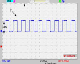


Fig. 7. Blocked voltage waveforms across switches of S1 (25V/div), S2 (100V/div), T1 (50V/div), T2 and T3 (100V/div) from left to right in the experiment
 

                                                                                           (a)  
                                                                                                        
                                                                                                (b)
Fig. 8. Output voltage and current waveforms for (a) inductive load in experiment (250 V/div & 2 A/div) (b) sudden step load in simulation


                                                                                                            (a)  


(b)

Fig. 9. Observed capacitors’ current (a) in simulation (b) in experiment (2A/div)


Fig. 10. (a) laboratory prototype (b) Output 49-level voltage and current waveforms in the experiment (250V/div & 2A/div)


Fig. 11. Across voltage waveforms of capacitors in upper and lower stages of SCCs in proposed 49-level inverter (a) v C 1 lower stage (5V/div) (b) v C 2 lower stage (10V/div) (c) v C 1 upper stage(25V/div) (d) v C 2 upper stage(50V/div)

CONCLUSION

In this paper, at the first, a new reduced components SCC topology was presented which has boost capability remarkably and also can pass the reverse current for inductive loads through existing power switches. The voltage of all capacitors in this structure is balanced by binary asymmetrical algorithm. Next, a new sub-multilevel structure based on suggested SCC was proposed which can generate all of the voltage levels at the output (even and odd). In this case, the conventional output H-bridge cell used to convert the polarity of SCC units, has been removed, therefore number of required IGBTs and other involved components, are decreased. After that, an optimizing  operation was presented which could obvious the number of required capacitors in each of SCC units that participate in the cascade sub-multilevel inverter (CSMLI) to generate maximum number of output voltage levels with less number of elements. Moreover comprehensive comparisons were given which prove the differences between improved symmetric and asymmetric CSMLIs in contrast to some of recently presented topologies in variety aspects. Finally, to confirm the performance and effectiveness of proposed CSMLI, several simulation and experimental results have been presented.

REFERENCES

[1] J. Chavarria, D. Biel, F. Guinjoan, C. Meza, and J. J. Negroni, “Energy balance control of PV cascaded multilevel grid-connected inverters under level-shifted and phase-shifted PWMs,” IEEE Trans. Ind. Electron. vol. 60, no. 1, pp. 98–111, Jan. 2013.
[2] G. Buticchi, E. Lorenzani, and G. Franceschini, “A five-level single-phase grid-connected converter for renewable distributed systems,” IEEE Trans. Ind. Electron., vol. 60, no. 3, pp. 906–918, Mar. 2013.
[3] J. Rodriguez, L. J.Sheng, and P. Fang Zheng, “Multilevel inverters: A survey of topologies, controls, and applications,” IEEE Trans. Ind Electron., vol. 49, no. 4, pp. 724–738, Aug. 2002.
[4] L. G. Franquelo, J. Rodriguez, J. I. Leon, S. Kouro, R. Portillo, and M. A. M. Prats, “The age of multilevel converters arrives,” IEEE Trans. Industrial Electronic Magazine, vol. 2, no. 2, pp. 28–39, Jun. 2008.
[5] M. M. Renge and H. M. Suryawanshi, “Five-Level Diode Clamped Inverter to Eliminate Common Mode Voltage and Reduce dv/dt in Medium Voltage Rating Induction Motor Drives,” IEEE Trans. Power Electron., vol. 23, no. 4, pp. 1598-1607, Jul. 2008.


Friday 10 March 2017

Fixed Switching Frequency Sliding Mode Control for Single-Phase Unipolar Inverters


ABSTRACT:
Sliding mode control (SMC) is recognized as robust controller with a high stability in a wide range of operating conditions, although it suffers from chattering problem. In addition, it cannot be directly applied to multi switches power converters. In this paper, a high performance and fixed switching frequency sliding mode controller is proposed for a single-phase unipolar inverter. The chattering problem of SMC is eliminated by smoothing the control law in a narrow boundary layer, and a pulse width modulator produces the fixed frequency switching law for the inverter. The smoothing procedure is based on limitation of pulse width modulator. Although the smoothed control law limits the performance of SMC, regulation and dynamic response of the inverter output voltage are in an acceptable superior range. The performance of the proposed controller is verified by both simulation and experiments on a prototype 6-kVA inverter. The experimental results show that the total harmonic distortion of the output voltage is less than 1.1% and 1.7% at maximum linear and nonlinear load, respectively. Furthermore, the output dynamic performance of the inverter strictly conforms the standard IEC62040-3. Moreover, the measured efficiency of the inverter in the worst condition is better than 95.5%.

KEYWORDS:
1.      Pulse width modulator
2.       Sliding mode control
3.      Unipolar single phase inverter

SOFTWARE: MATLAB/SIMULINK

BLOCK DIAGRAM:


Fig. 1. Proposed controller for single-phase inverters with a resonator in voltage
loop.

 EXPECTED SIMULATION RESULTS:


Fig. 2. Simulation result. a) Output voltage and current at 6-kW linear load. b) Output voltage and current at 6-kVA nonlinear load with CF = 2.75 and PF = +0.7.


Fig. 3. Simulation result: transient response of the output voltage for linear
step load from zero to 100%
.


Fig. 4. Simulation result: transient response of the output voltage for linear
step load from 100% to zero.


Fig. 5. Experimental result: efficiency of inverter versus output power.

CONCLUSION:

In this paper, a fixed frequency SMC was presented for a single-phase inverter. The performance of the proposed controller has been demonstrated by a 6-kVA prototype. Experimental results show that the inverter is categorized in class1 of the IEC64020-3 standard for output dynamic performance. The inverter efficiency was measured up to 95.5% in the worst case.
Since the direct SMC cannot be applied to four switches unipolar inverter and it also suffers from the chattering problem, a PWM is employed to generate a fixed frequency switching law. The PWM modulates the smoothed discontinuous control law which is produced by SMC. To smooth the control law, the limitation of the PWM was considered.
The simulation and experimental results show that the load regulation is about 1% at the steady state as well. But, to obtain better regulation, a resonance compensator was added in the voltage loop. With this compensator, the load regulation was measured which has been below 0.2%.

REFERENCES:

[1] G. Venkataramanan and D.M. Divan, “Discrete time integral sliding mode control for discrete pulse modulated converters,” in Proc. 21st Annu. IEEE Power Electron. Spec. Conf., San Antonio, TX, 1990, pp. 67–73.
[2] J.Y.Hung,W. Gao, and J. C.Hung, “Variable structure control:Asurvey,” IEEE Trans. Ind. Electron., vol. 40, no. 1, pp. 2–22, Feb. 1993.
[3] E. Fossas and A. Ras, “Second order sliding mode control of a buck converter,” in Proc. 41st IEEE Conf. Decision Control, 2002, pp. 346– 347.
[4] C. Rech, H. Pinheiro, H. A. Gr¨undling, H. L. Hey, and J. R. Pinheiro, “A modified discrete control law for UPS applications,” IEEE Trans. Power Electron., vol. 18, no. 5, pp. 1138–1145, Sep. 2003.
[5] K. S. Low, K. L. Zhou, and D.W.Wang, “Digital odd harmonic repetitive control of a single-phase PWM inverter,” in Proc. 30th Annu. Conf. IEEE Ind. Electron. Soc., Busan, Korea, Nov. 2–6, 2004, pp. 6–11.


Thursday 2 March 2017

An Efficient Modified CUK Converter with Fuzzy based Maximum Power Point Tracking Controller for PV System


 ABSTRACT:
To improve the performance of photovoltaic system a modified cuk converter with Maximum Power Point Tracker (MPPT) that uses a fuzzy logic control algorithm is presented in this research work. In the proposed cuk converter, the conduction losses and switching losses are reduced by means of replacing the passive elements with switched capacitors. These switched capacitors are used to provide smooth transition of voltage and current. So, the conversion efficiency of the converter is improved and the efficiency of the PV system is increased. The PV systems use a MPPT to continuously extract the highest possible power and deliver it to the load. MPPT consists of a dc-dc converter used to find and maintain operation at the maximum power point using a tracking algorithm. The simulated results indicate that a considerable amount of additional power can be extracted from photovoltaic module using a proposed converter with fuzzy logic controller based MPPT

KEYWORDS:

1.      Modified Cuk Converter
2.      Photovoltaic System
3.      Maximum Power Point Tracker
4.      Fuzzy Logic Controller

SOFTWARE: MATLAB/SIMULINK

CIRCUIT DIAGRAM:


                                                        Figure 1: Simulation diagram for the proposed converter

EXPECTED SIMULATION RESULTS:


(a)

(b)

(c)
Figure 2: Output of Solar Irradiation at 500 watts / m2 (a)
Current, (b) Voltage, (c) Power

(a)
(b)
(c)
Figure 3: Output of Solar Irradiation at 1000 watts / m2 (a)
Current, (b) Voltage, (c) Power

CONCLUSION:

The proposed modified cuk converter was simulated in MATLAB simulation platform and the output performance was evaluated. Then, the mode of operation of proposed converter was analyzed by the different solar irradiation level. From that, output current, voltage and power were considered. For evaluating the output performance, the proposed modified cuk converter output was tested with PV system. From the testing results, the output power of the modified converter efficiency and the efficiency deviation were analyzed. The analyses showed that the proposed modified cuk converter was better when compared to conventional cuk converter and boost converter. Experimental setup has been done to prove the effectiveness of the proposed system.

REFERENCES:

1. Singh R & Sood Y R, Transmission tariff for restructured Indian power sector with special consideration to promotion of renewable energy sources, IEEE Region 10 Conference, TENCON, (2009), 1 – 7.
2. Xia Xintao & Xia Junzi, Evaluation of Potential for Developing Renewable Sources of Energy to Facilitate Development in Developing Countries, Asia-Pacific Power and Energy Engineering Conference (APPEEC), (2010), 1 – 3.
3. Hosseini R & Hosseini N & Khorasanizadeh H, An experimental study of combining a photovoltaic system with a heating system, World Renewable Energy Congress, 8 (2011), 2993-3000.
4. Shakil Ahamed Khan & Md. Ismail Hossain, Design and Implementation of Microcontroller Based Fuzzy Logic Control for Maximum Power Point Tracking of a Photovoltaic System, IEEE International Conference on Electrical and Computer Engineering, Dhaka, (2010), 322-325.

5. Pradeep Kumar Yadav A, Thirumaliah S & Haritha G, Comparison of MPPT Algorithms for DC-DC Converters Based PV Systems, International Journal of Advanced Research in Electrical, Electronics and Instrumentation Engineering, 1 (2012), 18-23.