ABSTRACT:
Here,
we have studied the voltage quality improvement methods by using Dynamic
Voltage Restorer (DVR), Distribution Static Synchronous Compensator (D-STATCOM)
and Unified Power Quality Conditioner (UPQC) using two different controller
Strategies. The controllers used are Proportional Integral Controller (PIC) and
Fuzzy Logic Controller (FLC). A PI Controller
calculates an error value as the difference between a measured variable and
desired set point. The fuzzy logic controller has real time inputs measured at
every sample time, named error and error rate and one output named actuating signal
for each phase. The input signals are fuzzified and represented in fuzzy set
notations as functions. The defined 'If ... Then .. .' rules produce output
actuating signals and these signals are defuzzified to analog control signals
for comparing with a carrier signal to control PWM inverter.
KEYWORDS:
1. Dynamic
Voltage Restorer (DVR)
2. Distribution
Static Synchronous Compensator (D-STATCOM)
3. Unified
Power Quality Conditioner (UPQC)
4. Power
Quality
5. PI Controller
6. Fuzzy
Controller and MATLAB
SOFTWARE: MATLAB/SIMULINK
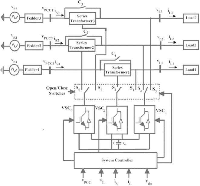
BLOCK DIAGRAM:

Fig
1. The equivalent circuit diagram of DVR

Fig
2. The equivalent circuit diagram of DST A TCOM

Fig 3.The
circuit diagram of UPQC
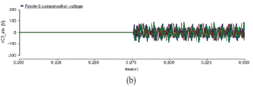
EXPECTED SIMULATION RESULTS:

Fig
4. Input voltage and input current waveform without compensation

Fig
5. Load voltage and load current waveform without compensation

Fig
6. load voltage and load current waveform after compensation(DVR)

Fig
7. Output load voltage without compensation

Fig
8. Output load voltage with compensation using FLC

Fig
9.load voltage and load current waveform after compensation (D-STATCOM)

Fig
10. Load voltage and load current waveform after compensation (D-STATCOM)

Fig 11.
Load voltage and load current waveform for UPQC with
PI Controller.

Fig 12
Load voltage and load current waveform with compensation
CONCLUSION:
In
this paper, we have studied the series, shunt and series shunt compensators.
Performance analysis has been done by comparing the power quality using each compensator.
The performance of DVR has been analyzed with PI controller the load voltage
during fault is almost equal to the desired load voltage. Load current
magnitude is almost equal but still there are some imbalances between the
phases for a small duration of time. DVR have been found to regulate voltage
under Fuzzy Logic controller. It is clear that DVR reduces harmonics from load
voltage very effectively and makes it smooth. Hence, it is concluded that DVR
has a huge scope in improving power quality in distribution systems. DSTATCOM
is proved to compensate voltage levels under faulty conditions. Using PI
controller, harmonics have been reduced considerably. But current got
unbalanced for the entire duration of time. By using the Fuzzy Logic Controller
instead of the PI Controller gives better transient response. The DC Link
voltage is suddenly increased above the reference value. And it is brought back
to its reference value. A good voltage control is also achieved by implementing
Fuzzy logic control. Also the steady state is reached faster. The control
strategies of UPQC were described and compared with respect to its performance
through simulation. The power quality issues are almost reduced. The closed
loop control schemes of current control, for the proposed UPQC have been investigated.
Total harmonic distortion was analyzed and it describes that the UPQC with
fuzzy controller provides more efficiency than the other strategies.
[1]
Smriti De)'. Comparison of DVR and D-STATCOM for Voltage (",)uality
Improvement, [JET AE (ISSN 2250- 2459), Vol 4, Issue 10, October 2014, PP
187-193.
[2]
Ganeshkumar.A, Ananthan.N, Performance Comparison Of UPQC For Improving The
Power Quality With Various Controllers Strategy ,IJETCSE, Vol 13 Issue 2, March2015,PP
12-17.
[3]
Shipra Pandey, Dr. S.Chatterji, Ritula Thakur. Fuzzy Controlled DSTATCOM for
Voltage Sag Compensation and DC-Link Voltage Improvement. [JEECS , ,Vol 3, Issue
I, April 2014.
[4]
C. Sankaran "Power Quality", CRC Press 2002.
[5]
N.G. Hingorani and L Gyugyi, Understanding FACTS - Concepts and Technology OF
Flexible AC Transmission Systems, IEEE Press, New York, 2000.