asokatechnologies@gmail.com 09347143789/09949240245

Search This Blog

Saturday 26 January 2019

Control of Induction Motor Drive using Space Vector PWM


 ABSTRACT:  
In this paper speed of induction motor is controlled which is fed from three phase bridge inverter. In this paper the speed of an induction motor can be varied by varying input Voltage or frequency or both. Variable voltage and variable frequency for Adjustable Speed Drives (ASD) is invariably obtained from a three-phase Voltage Source Inverter (VSI). Voltage and frequency of inverter can be easily controlled by using PWM techniques, which is a very important aspect in the application of ASDs. A number of PWM techniques are there to obtain variable voltage and variable frequency supply such as PWM, SPWM, SVPWM to name a few, among the various modulation strategies SVPWM is one of the most efficient techniques as it has better performance and output voltage is similar to sinusoidal. In SVPWM the modulation index in linear region will also be high when compared to other
KEYWORDS:
1.      Adjustable Speed Drive (ASD)
2.      Voltage source inverter (VSI)
3.      Sinusoidal PWM (SPWM)
4.      Space Vector PWM (SVPWM)

SOFTWARE: MATLAB/SIMULINK

 BLOCK DIAGRAM:


 Figure 1: ASD Block Diagram

 EXPECTED SIMULATION RESULTS:


Figure 2: SPWM Pulses


Figure 3: Inverter o/p line voltages
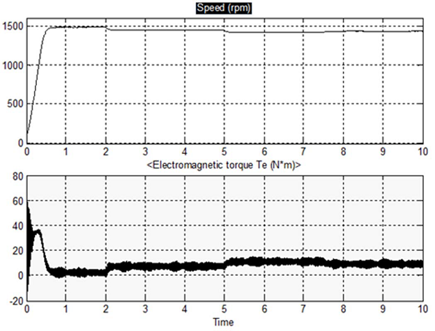


Figure 4: Motor Speed and Electromagnetic torque.


Figure 5: SVPWM output gate pulses


Figure 6:Open Loop Drive Speed response with TL=0


Figure 7: Open Loop Drive Speed response with different TL


Figure 8: SPWM based open loop drive Load Current THD

 CONCLUSION:
 The simulation of “Control of Induction Motor Drive Using Space Vector PWM” is carried out in MATLAB/Simulink. The simulation has been done for open loop as well as closed control. The appropriate output results are obtained. The variation of speed of Induction Motor has been observed by varying the load torque in open loop control and results are noted down in the table. Also observed that for the change in input speed commands the motor speed is settled down to its final value within 0.1sec in closed loop model.
REFERENCES:
[1] Abdelfatah Kolli, Student Member, IEEE, Olivier Béthoux, Member, IEEE, Alexandre De Bernardinis, Member, IEEE, Eric Labouré, and Gérard Coquery “Space-Vector PWM Control Synthesis for an H-Bridge Drive in Electric Vehicles” IEEE TRANSACTIONS ON VEHICULAR TECHNOLOGY, VOL. 62, NO. 6, JULY 2013. pp. 2241-2252.
[2]Mr. Sandeep N Panchal, Mr. Vishal S Sheth, Mr. Akshay A Pandya “Simulation Analysis of SVPWM Inverter Fed Induction Motor Drives” International Journal of Emerging Trends in Electrical and Electronics (IJETEE) Vol. 2, Issue. 4, April-2013. pp. 18-22 .
[3]Haoran Shi, Wei Xu, Chenghua Fu and Yao Yang. “Research on Threephase Voltage Type PWM Rectifier System Based on SVPWM Control” Research Journal of Applied Sciences, Engineering and Technology 5(12): 3364-3371, 2013. pp. 3364-3371.
[4]K. Mounika, B. Kiran Babu, “Sinusoidal and Space Vector Pulse Width Modulation for Inverter” International Journal of Engineering Trends and Technology (IJETT) - Volume4Issue4- April 2013. pp.1012-1017.
[5]K. Vinoth Kumar, Prawin Angel Michael, Joseph P. John and Dr. S. Suresh Kumar. “Simulation And Comparison Of Spwm And Svpwm Control For Three Phase Inverter” ARPN Journal of Engineering and Applied Sciences VOL. 5, NO. 7, JULY 2010. pp. 61-74.

Thursday 24 January 2019

A Novel Multilevel Inverter Based on Switched DC Sources


ABSTRACT:  
This paper presents a multilevel inverter that has been conceptualized to reduce component count, particularly for a large number of output levels. It comprises floating input dc sources alternately connected in opposite polarities with one another through power switches. Each input dc level appears in the stepped load voltage either individually or in additive combinations with other input levels. This approach results in reduced number of power switches as compared to classical topologies. The working principle of the proposed topology is demonstrated with the help of a single-phase five-level inverter. The topology is investigated through simulations and validated experimentally on a laboratory prototype. An exhaustive comparison of the proposed topology is made against the classical cascaded H-bridge topology.

KEYWORDS:
1.      Classical topologies
2.      Multilevel inverter (MLI)
3.      Pulse width modulation (PWM)
4.      Reduced component count
5.       Total harmonic distortion (THD)

SOFTWARE: MATLAB/SIMULINK

 CIRCUIT DIAGRAM:


Fig. 1. Single-phase inverter based on the proposed topology with two input
sources.


EXPECTED SIMULATION RESULTS:


Fig. 2. (a) Reference and carrier waveforms for the proposed scheme for a
five-level output. (b) Aggregated signal “a(t).”


Fig. 3. Switching pulse pattern for the five-level inverter.


Fig. 4. Simulation results. (a) Five-level voltage output. (b) Harmonic spectrum
of the load voltage.


Fig. 5. Simulation results. (a) Load current waveform with an RL load (R =
2 Ω and L = 2 mH). (b) Harmonic spectrum of the load current.

 CONCLUSION:

As MLIs are gaining interest, efforts are being directed toward reducing the device count for increased number of output levels. A novel topology for MLIs has been proposed in this paper to reduce the device count. The working principle of the proposed topology has been explained, and mathematical formulations corresponding to output voltage, source currents, voltage stresses on switches, and power losses have been developed. Simulation studies performed on a five-level inverter based on the proposed structure have been validated experimentally. Comparison of the proposed topology with conventional topologies reveals that the proposed topology significantly reduces the number of power switches and associated gate driver circuits. Analytical comparisons on the basis of losses and switch cost indicate that the proposed topology is highly competitive. The proposed topology can be effectively employed for applications where isolated dc sources are available. The advantage of the reduction in the device count, however, imposes two limitations: 1) requirement of isolated dc sources as is the case with the CHB topology and 2) curtailed modularity and fault-tolerant capabilities as compared to the CHB topology.
REFERENCES:
[1] S. Kouro, M. Malinowski, K. Gopakumar, J. Pou, L. Franquelo, B. Wu, J. Rodriguez, M. Perez, and J. Leon, “Recent advances and industrial applications of multilevel converters,” IEEE Trans. Ind. Electron., vol. 57, no. 8, pp. 2553–2580, Aug. 2010.
[2] G. Buticchi, E. Lorenzani, and G. Franceschini, “A five-level single-phase grid-connected converter for renewable distributed systems,” IEEE Trans. Ind. Electron., vol. 60, no. 3, pp. 906–918, Mar. 2013.
[3] J. Rodriguez, J.-S. Lai, and F. ZhengPeng, “Multilevel inverters: A survey of topologies, controls, applications,” IEEE Trans. Ind. Electron., vol. 49, no. 4, pp. 724–738, Aug. 2002.
[4] S. De, D. Banerjee, K. Siva Kumar, K. Gopakumar, R. Ramchand, and C. Patel, “Multilevel inverters for low-power application,” IET Power Electronics, vol. 4, no. 4, pp. 384–392, Apr. 2011.
[5] M. Malinowski, K. Gopakumar, J. Rodriguez, and M. A. Pérez, “A survey on cascaded multilevel inverters,” IEEE Trans. Ind. Electron., vol. 57, no. 7, pp. 2197–2206, Jul. 2010.

Tuesday 15 January 2019

Electric Spring for Voltage and Power Stability and Power Factor Correction


ABSTRACT:  
Electric Spring (ES), a new smart grid technology, has earlier been used for providing voltage and power stability in a weakly regulated/stand-alone renewable energy source powered grid. It has been proposed as a demand side management technique to provide voltage and power regulation. In this paper, a new control scheme is presented for the implementation of the electric spring, in conjunction with non-critical building loads like electric heaters, refrigerators and central air conditioning system. This control scheme would be able to provide power factor correction of the system, voltage support, and power balance for the critical loads, such as the building's security system, in addition to the existing characteristics of electric spring of voltage and power stability. The proposed control scheme is compared with original ES’s control scheme where only reactive-power is injected. The improvised control scheme opens new avenues for the utilization of the electric spring to a greater extent by providing voltage and power stability and enhancing the power quality in the renewable energy powered microgrids.
KEYWORDS:
1.      Demand Side Management
2.      Electric Spring
3.      Power Quality
4.      Single Phase Inverter
5.      Renewable Energy
SOFTWARE: MATLAB/SIMULINK

BLOCK DIAGRAM:


Fig. 1. Electric Spring in a circuit


EXPECTED SIMULATION RESULTS:


Fig. 2. Over-voltage, Conventional ES: Power Factor of system (ES turned on at t = 0.5 sec)


Fig. 3. Over-voltage, Conventional ES: Active and Reactive power across critical load, non-critical load, and electric spring (ES turned on at t=0.5 sec)


Fig. 4 Under-voltage, Conventional ES: RMS Line voltage, ES Voltage, and
Non-Critical load voltage (ES turned on at t=0.5 sec)


Fig. 5. Under-voltage, Conventional ES: Power Factor of system (ES turned on at t = 0.5 sec)

Fig. 6. Under-voltage, Conventional ES: Active and Reactive power across critical load, non-critical load, and electric spring (ES turned on at t=0.5 sec)

Fig. 7. Over-voltage, Improvised ES: RMS Line voltage, ES Voltage, and Non-Critical load voltage (ES turned on at t=0.5 sec)


Fig. 8. Over-voltage, Improvised ES: Power Factor of system (ES turned on at t = 0.5 sec)


Fig. 9. Over-voltage, Improvised ES: Active and Reactive power across critical load, non-critical load, and electric spring (ES turned on at t=0.5 sec)

Fig. 10. Under-voltage, Improvised ES: RMS Line voltage, ES Voltage, and
Non-Critical load voltage (ES turned on at t=0.5 sec)
Fig. 11. Under-voltage, Improvised ES: Power Factor of system (ES turned
on at t = 0.5 sec)
Fig. 12. Under-voltage, Improvised ES: Active and Reactive power across critical load, non-critical load, and electric spring (ES turned on at t=0.5 sec)

CONCLUSION:

In this paper as well as earlier literatures, the Electric Spring was demonstrated as an ingenious solution to the problem of voltage and power instability associated with renewable energy powered grids. Further in this paper, by the implementation of the proposed improvised control scheme it was demonstrated that the improvised Electric Spring (a) maintained line voltage to reference voltage of 230 Volt, (b) maintained constant power to the critical load, and (c) improved overall power factor of the system compared to the conventional ES. Also, the proposed ‘input-voltage-input-current’ control scheme is compared to the conventional ‘input-voltage’ control. It was shown, through simulation and hardware-in-loop emulation, that using a single device voltage and power regulation and power quality improvement can be achieved. It was also shown that the improvised control scheme has merit over the conventional ES with only reactive power injection. Also, it is proposed that electric spring could be embedded in future home appliances [1]. If many non-critical loads in the buildings are equipped with ES, they could provide a reliable and effective solution to voltage and power stability and insitu power factor correction in a renewable energy powered microgrids. It would be a unique demand side management (DSM) solution which could be implemented without any reliance on information and communication technologies.
REFERENCES:
[1] S. Y. Hui, C. K. Lee, and F. F. Wu, “Electric springs - a new smart grid technology,” IEEE Transactions on Smart Grid, vol. 3, no. 3, pp. 1552–1561, Sept 2012.
[2] S. Hui, C. Lee, and F. WU, “Power control circuit and method for stabilizing a power supply,” 2012. [Online]. Available: http://www.google.com/patents/US20120080420
[3] C. K. Lee, N. R. Chaudhuri, B. Chaudhuri, and S. Y. R. Hui, “Droop control of distributed electric springs for stabilizing future power grid,” IEEE Transactions on Smart Grid, vol. 4, no. 3, pp. 1558–1566, Sept 2013.
[4] C. K. Lee, B. Chaudhuri, and S. Y. Hui, “Hardware and control implementation of electric springs for stabilizing future smart grid with intermittent renewable energy sources,” IEEE Journal of Emerging and Selected Topics in Power Electronics, vol. 1, no. 1, pp. 18–27, March 2013.
[5] C. K. Lee, K. L. Cheng, and W. M. Ng, “Load characterisation of electric spring,” in 2013 IEEE Energy Conversion Congress and Exposition, Sept 2013, pp. 4665–4670.