asokatechnologies@gmail.com 09347143789/09949240245

Search This Blog

Saturday 26 February 2022

Design of a New Combined Cascaded Multilevel Inverter Based on Developed H-Bridge with Reduced Number of IGBTs and DC Voltage Sources

 ABSTRACT:

In this paper, a new combined cascaded multilevel inverter with reduced number of switches and DC voltage sources which is formed by series connection of same units with developed H-Bridge is proposed. For the purpose of generating all even and odd voltage levels 5 algorithms to determine the magnitudes of DC voltage sources is proposed. In order to investigate the advantages and disadvantages of the proposed combined cascaded multilevel inverter the proposed algorithms are compared to presented topologies from different points of view. The experimental results of the proposed topology are stated to check and verifying the performance of the proposed topology.

KEYWORDS:

1.      Multilevel inverter

2.      Cascaded multilevel inverter

3.      Combined topology

4.      Developed H-Bridge

SOFTWARE: MATLAB/SIMULINK

 CIRCUIT DIAGRAM:


Fig. 1. Basic topology of proposed multilevel inverter.

EXPECTED SIMULATION RESULTS:


Fig. 2. Experimental results; (a) output voltage; (b) output voltage and current; (c) generated voltage levels by right side; (d) generated voltage levels by left side; (e) generated voltage levels by L,1 u ; (f) voltage across R2,2 S ; (g) voltage across 1 T ; (h) voltage across 3 T ; (i) voltage across a T .

CONCLUSION:

 In this paper, a new combined cascaded multilevel inverter has been proposed. After that, five different algorithms are proposed in order to determine the magnitudes of the DC voltage sources. By comparing these algorithms, it was concluded that the algorithm which generates a high number of voltage levels with less number of switches and DC voltage sources is better than other algorithms. According to this comparison, it was found that the fifth proposed algorithm is better among the proposed algorithms. In order to prove the claim about reduction of the number of IGBTs and DC voltage sources in the proposed topology, this topology was compared to presented topologies from different aspects. In these comparisons, it was found that the proposed topology generates 31 voltage levels with 14 IGBTs while presented topologies in [4], [10] and [12] generate the same number of voltage levels with 32, 16 and 34 IGBTs, respectively. Also, it was found that this number of voltage levels needs 4 DC voltage sources, whereas, the topologies which presented in [4] and [12] generate 17 and 9 voltage levels with the same number of DC voltage sources. Afterwards, correctness of performance of the proposed topology and relations have been verified through experimentation of the proposed topology with 2 input units in each side.

REFERENCES:

[1] C.I. Odeh, E.S. Obe, and O. Ojo,: “Topology for cascaded multilevel inverter,” IET Power Electron., vol. 9, no. 5, pp. 921-929, April 2016.

[2] E. Zamiri, N. Vosoughi, S.H. Hosseini, R. Barzegarkhoo, and M. Sabahi, “A new cascaded switched-capacitor multilevel inverter based on improved series–parallel conversion with less number of components,” IEEE Trans. Ind. Electron., vol. 63, no. 6, pp. 3582-3594, June 2016.

[3] N. Prabaharan and K. Palanisamy, “Analysis of cascaded H-bridge multilevel inverter configuration with double level circuit,” IET Power Electron., vol. 10, no. 9, pp. 1023-1033, July 2017.

[4] M.R. Banaei, M.R. Jannati Oskuee and H. Khounjahan, “Reconfiguration of semi-cascaded multilevel inverter to improve systems performance parameters,” IET Power Electron., vol. 7, no. 5, pp. 1106-1112, May 2014.

[5] E. Babaei, S. Laali, and Z. Bayat, “A single-phase cascaded multilevel inverter based on a new basic unit with reduced number of power switches,” IEEE Trans. Ind. Electron., vol. 62, no. 2, pp. 922-929, Feb. 2015.

Design and Performance Analysis of Three-Phase Solar PV Integrated UPQC

 ABSTRACT:

This paper deals with the design and performance analysis of a three-phase single stage solar photovoltaic integrated unified power quality conditioner (PV-UPQC). The PV-UPQC consists of a shunt and series connected voltage compensators connected back to back with common DC-link.The shunt compensator performs the dual function of extracting power from PV array apart from compensating for load current harmonics. An improved synchronous reference frame control based on moving average filter is used for extraction of load active current component for improved performance of the PVUPQC. The series compensator compensates for the grid side power quality problems such as grid voltage sags/swells. The compensator injects voltage in-phase/out of phase with point of common coupling (PCC) voltage during sag and swell conditions respectively. The proposed system combines both the benefits of clean energy generation along with improving power quality. The steady state and dynamic performance of the system are evaluated by simulating in Matlab-Simulink under a nonlinear load. The system performance is then verified using a scaled down laboratory prototype under a number of disturbances such as load unbalancing, PCC voltage sags/swells and irradiation variation.

KEYWORDS:

1.      Power Quality

2.      Shunt compensator

3.      Series compensator

4.      UPQC

5.      Solar PV

6.       MPPT

SOFTWARE: MATLAB/SIMULINK

CIRCUIT DIAGRAM:

Fig. 1. System Configuration PV-UPQC

 EXPECTED SIMULATION RESULTS:


Fig. 2. Performance of PV-UPQC under Voltage Sag and Swell Conditions

Fig. 3. Performance PV-UPQC during Load Unbalance Condition


Fig. 4. Performance PV-UPQC at Varying Irradiation Condition


Fig. 5. Load Current Harmonic Spectrum and THD

Fig. 6. Grid Current Harmonic Spectrum and THD

CONCLUSION:

 The design and dynamic performance of three-phase PVUPQC have been analyzed under conditions of variable irradiation and grid voltage sags/swells. The performance of the system has been validated through experimentation on scaled down laboratory prototype. It is observed that PVUPQC mitigates the harmonics caused by nonlinear load and maintains the THD of grid current under limits of IEEE-519 standard. The system is found to be stable under variation of irradiation, voltage sags/swell and load unbalance. The performance of d-q control particularly in load unbalanced condition has been improved through the use of moving average filter. It can be seen that PV-UPQC is a good solution for modern distribution system by integrating distributed generation with power quality improvement.

REFERENCES:

[1] B. Mountain and P. Szuster, “Solar, solar everywhere: Opportunities and challenges for australia’s rooftop pv systems,” IEEE Power and Energy Magazine, vol. 13, no. 4, pp. 53–60, July 2015.

[2] A. R. Malekpour, A. Pahwa, A. Malekpour, and B. Natarajan, “Hierarchical architecture for integration of rooftop pv in smart distribution systems,” IEEE Transactions on Smart Grid, vol. PP, no. 99, pp. 1–1, 2017.

[3] Y. Yang, P. Enjeti, F. Blaabjerg, and H. Wang, “Wide-scale adoption of photovoltaic energy: Grid code modifications are explored in the distribution grid,” IEEE Ind. Appl. Mag., vol. 21, no. 5, pp. 21–31, Sept 2015.

[4] M. J. E. Alam, K. M. Muttaqi, and D. Sutanto, “An approach for online assessment of rooftop solar pv impacts on low-voltage distribution networks,” IEEE Transactions on Sustainable Energy, vol. 5, no. 2, pp. 663–672, April 2014.

[5] J. Jayachandran and R. M. Sachithanandam, “Neural network-based control algorithm for DSTATCOM under nonideal source voltage and varying load conditions,” Canadian Journal of Electrical and Computer Engineering, vol. 38, no. 4, pp. 307–317, Fall 2015.

Design and Control of SR Drive System using ANFIS

 ABSTRACT:

This paper presents the modeling and simulation of an adaptive neuro-fuzzy inference strategy (ANFIS) to control the speed of the switched Reluctance motor .The SRM control is thus a difficult to be in use in the nonlinear applications, particularly in the control of speed in automobiles. The Neuro-fuzzy system incorporates the advantages of both neural-network and fuzzy system. This controller is great additional effectual than Fuzzy logic and neural network based controller, while it has the ability of self-learning the gain values and acclimatizes accordingly to situations, thus accumulating more flexibility to the controller. A complete simulation, well-designed to the nonlinear model of Switched Reluctance Drive was premeditated using MATLAB /SIMULINK.

KEYWORDS:

1.      SR Drive

2.      ANFIS

3.      ANN

4.      FLC

SOFTWARE: MATLAB/SIMULINK

 BLOCK DIAGRAM:


Fig.1.Block Diagram of ANFIS Controller for SRM Plant

EXPECTED SIMULATION RESULTS:


Fig.2: Response of the speed control of SRM using FUZZY, ANN and ANFIS with speed Command 3000 RPM under no load conditions.


Fig.3: Response of the Speed and Torque Control of SRM using ANFIS with Speed Command 3000 Rpm under no load conditions.


Fig.4: Response of The Speed and Torque Control of SRM using Fuzzy, ANN and ANFIS with Speed command 4000 rpm.


Fig.5: Response of the Speed and Torque Control of SRM using ANFIS with Speed Command 4000 rpm.

Fig.6: Response of the speed control of SRM using FUZZY, ANN and ANFIS with speed Command 3000 RPM under load Conditions

Fig.7: Response of the speed and torque control of SRM using ANFIS with speed

 CONCLUSION:

 In this paper, ANFIS-based controller was presented for SR drives. The speed and torque control method existing in this paper and comparing with the previous control schemes(fuzzy &ANN), while it can be used in both no load and load operating speeds and conditions including speed and torque transients, zero-speed standstill, and startup, and does not suppose the linear characteristics of the SR motor. Moreover, the proposed technique does not need of complex calculations to be carried out during the real-time operation, and no complex mathematical model of the SR motor is required. A main thought in the research was the robustness and reliability of the speed controlling method.

REFERENCES:

[1] J. P. Lyons, S. R. MacMinn, and M. A. Preston, “Flux/current methods for SRM rotor position estimation,” in Proc. IEEE Industry Application Soc. Annu. Meeting, vol. 1, 1991, pp. 482–487.

[2]S. R. MacMinn, C. M. Steplins, and P. M. Szaresny, “Switched reluctance motor drive system and laundering apparatus employing same,” U.S. Patent 4 959 596, 1989.

[3] M. Ehsani, I. Husain, S. Mahajan, and K. R. Ramani, “New modulation encoding techniques for indirect rotor position sensing in switched reluctance motors,” IEEE Trans. Ind. Applicat., vol. 30, pp. 85–91, Jan./Feb. 1994.

[4] G. R. Dunlop and J. D. Marvelly, “Evaluation of a self commuted switched reluctance motor,” in Proc. Electric Energy Conf., 1987, pp. 317– 320.

[5]Ramesh.Palakeerthi,Subbaiah.P ,2014, ‘High Speed Charging and Discharging Current Controller Circuit to Reduce Back EMF by NeuroFuzzy Logic ‘, International Journal of Applied Engineering Research,vol. 9, no.22


An Efficient UPF Rectifier for a Stand-Alone Wind Energy Conversion System

ABSTRACT:

This project presents a near-unity-power-factor frontend rectifier employing two current control methods, namely, average current control and hysteresis current control, is considered. This rectifier is interfaced with a fixed-pitch wind turbine driving a permanent-magnet synchronous generator. A traditional diode-bridge rectifier without any current control is used to compare the performance with the proposed converter. Two constant wind speed conditions and a varying wind speed profile are used to study the performance of this converter for a rated stand-alone load. The parameters under study are the input power factor and total harmonic distortion of the input currents to the converter. The wind turbine generator–power electronic converter is modeled in PSIM, and the simulation results verify the efficacy of the system in delivering satisfactory performance for the conditions discussed. The efficacy of the control techniques is validated with a 1.5-kW laboratory prototype, and the experimental results are presented.

 KEYWORDS:

1.      Packed U-Cell Inverter

2.      Nine-level converter

3.      Single carrier modulation

4.      SiC switch

 SOFTWARE: MATLAB/SIMULINK

 BLOCK DIAGRAM:

Figure 1. Block diagram of a fixed speed wind energy system including a conventional SCIG, a gearbox and a transformer.

 EXPECTED SIMULATION RESULTS:


CONCLUSION:

 In this paper, a WECS interfaced with a UPF converter feeding a stand-alone load has been investigated. The use of simple bidirectional switches in the three-phase converter results in near-UPF operation. Two current control methods, i.e., ACC and HCC, have been employed to perform active input line current shaping, and their performances have been compared for different wind speed conditions. and further the performance can be improved with the Phased locked loop (PLL) and in future with the improved phased locked loop can be implemented for high levels of voltages and variable loads where phase locked loop is simple and reliable solution The quality of the line currents at the input of the converter is good, and the harmonic distortions are within the prescribed limits according to the IEEE 519 standard for a stand-alone system. A high power factor is achieved at the input of the converter, and the voltage maintained at the dc bus link shows excellent voltage balance. The proposed method yields better performance compared to a traditional uncontrolled diode bridge rectifier system typically employed in wind systems as the front-end converter. Finally, a laboratory prototype of the UPF converter driving a stand-alone load has been developed, and the ACC and HCC current control methods have been tested for comparison. The HCC current control technique was found to be superior and has better voltage balancing ability. It can thus be an excellent front-end converter in a WECS for stand-alone loads or grid connection.

REFERENCES:

[1] Aditya Venkataraman, Student Member, IEEE, Ali I. Maswood, Senior Member, IEEE, Nirnaya Sarangan, and Ooi H. P. Gabriel, Student Member, IEEE "An Efficient UPF Rectifier for a Stand-Alone Wind Energy Conversion System" IEEE TRANSACTIONS ON INDUSTRY APPLICATIONS, VOL. 50, NO. 2, MARCH/APRIL 2014

[2] Online. Available: http://en.wikipedia.org/wiki/Wind_energy

[3] M. Druga, C. Nichita, G. Barakat, B. Dakyo, and E. Ceanga, ―A peak power tracking wind system operating with a controlled load structure for stand-alone applications,‖ in Proc. 13th EPE, 2009, pp. 1–9.

[4] S. Kim, P. Enjeti, D. Rendusara, and I. J. Pitel, ―A new method to improve THD and reduce harmonics generated by a three phase diode rectifier type utility interface,‖ in Conf. Rec. IEEE IAS Annu. Meeting, 1994, vol. 2, pp. 1071–1077.

[5] A. I. Maswood and L. Fangrui, ―A novel unity power factor input stage for AC drive application,‖ IEEE Trans. Power Electron., vol. 20, no. 4, pp. 839–846, Jul. 2005.

Thursday 24 February 2022

A Switched-Capacitor Inverter Using Series/Parallel Conversion With Inductive Load

 ABSTRACT:

A novel switched-capacitor inverter is proposed. The proposed inverter outputs larger voltage than the input voltage by switching the capacitors in series and in parallel. The maximum output voltage is determined by the number of the capacitors. The proposed inverter, which does not need any inductors, can be smaller than a conventional two-stage unit which consists of a boost converter and an inverter bridge. Its output harmonics are reduced compared to a conventional voltage source single phase full bridge inverter. In this paper, the circuit configuration, the theoretical operation, the simulation results with MATLAB/ SIMULINK, and the experimental results are shown. The experimental results accorded with the theoretical calculation and the simulation results.

 KEYWORDS:

1.      Charge pump

2.      Multicarrier PWM

3.      Multilevel inverter

4.      Switched capacitor (SC)

 SOFTWARE: MATLAB/SIMULINK

 CIRCUIT DIAGRAM:


Fig. 1. Circuit topology of the switched-capacitor inverter using series/ parallel conversion.

 EXPECTED SIMULATION RESULTS:


Fig. 2. Simulated voltage waveforms of the proposed inverter (n = 2) designed for low power at 5.76 [W], switching  frequency f = 40 [kHz] and reference waveform frequency fref = 1 [kHz]. (a) Bus voltage waveform vbus and (b) the output voltage waveform vout.


Fig. 3. Simulated voltage waveforms of the proposed inverter (n = 2) designed for high power at 4.50 [kW], switching frequency f = 40 [kHz] and reference waveform frequency fref = 1 [kHz]. (a) Bus voltage waveform vbus and (b) the output voltage waveform vout.


Fig. 4. Simulated current waveforms of the capacitor iC1 in the proposed inverter (n = 2).(a) Designed for low power at 5.76 [W] and (b) designed for high power at 4.50 [kW].


Fig. 5. Simulated spectra of the bus voltage waveform of the proposed inverters (n = 2) normalized with the fundamental component. (a) Designed for low power at 5.76 [W] and (b) designed for high power at 4.50 [kW].


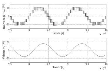
 Fig. 6. Simulated bus voltage waveforms vbus and the voltage waveforms of the load resistance vR of the proposed inverter (n = 2) designed for low power at 5.76 [W] with an inductive load.


CONCLUSION:

 In this paper, a novel boost switched-capacitor inverter was proposed. The circuit topology was introduced. The modulation method, the determination method of the capacitance, and the loss calculation of the proposed inverter were shown. The circuit operation of the proposed inverter was confirmed by the simulation results and the experimental results with a resistive load and an inductive load. The proposed inverter outputs a larger voltage than the input voltage by switching the capacitors in series and in parallel. The inverter can operate with an inductive load. The structure of the inverter is simpler than the conventional switched-capacitor inverters. THD of the output waveform of the inverter is reduced compared to the conventional single phase full bridge inverter as the conventional multilevel inverter.

REFERENCES:

[1] H. Liu, L. M. Tolbert, S. Khomfoi, B. Ozpineci, and Z. Du, “Hybrid cascaded multilevel inverter with PWM control method,” in Proc. IEEE Power Electron. Spec. Conf., Jun. 2008, pp. 162–166.

[2] A. Emadi, S. S. Williamson, and A. Khaligh, “Power electronics intensive solutions for advanced electric, hybrid electric, and fuel cell vehicular power systems,” IEEE Trans. Power Electron., vol. 21, no. 3, pp. 567–577, May 2006.

[3] L. G. Franquelo, J. Rodriguez, J. I. Leon, S. Kouro, R. Portillo, and M. A. M. Prats, “The age of multilevel converters arrives,” IEEE Ind. Electron. Mag., vol. 2, no. 2, pp. 28–39, Jun. 2008.

[4] Y. Hinago and H. Koizumi, “A single phase multilevel inverter using switched series/parallel DC voltage sources,” IEEE Trans. Ind. Electron., vol. 57, no. 8, pp. 2643–2650, Aug. 2010.

[5] S. Chandrasekaran and L. U. Gokdere, “Integrated magnetics for interleaved DC–DC boost converter for fuel cell powered vehicles,” in Proc. IEEE Power Electron. Spec. Conf., Jun. 2004, pp. 356–361.