ABSTRACT:
Micro-inverters operating into the single-phase grid
from new energy source with low-voltage output face the challenges of
efficiency bottleneck and twice-line-frequency variation. This paper proposed a
multilevel inverter based on bridge modular switched-capacitor (BMSC) circuits
with its superiority in conversion efficiency and power density. The topology
is composed of DC-DC and DC-AC stages with independent control for each stage,
aiming to improve system stability and simplify the control method. The BMSC
DC-DC stage, which can be expanded to synthesize more levels, not only features
multilevel voltage gain but also partially replaces the original bulk input
capacitor and functions as an active energy buffer to enhance power decoupling
ability between DC and AC sides. In DC-AC stage, the control strategy of
optimized unipolar frequency doubling sine-wave pulse-width modulation
(UFD-SPWM) is proposed to improve the
quality of output waveform. Meanwhile, the multilevel voltage phase has been
optimized to reduce the power loss further. Finally, a prototype has been built
and tested. Associated with the simulation, the experimental results validate
the practicability of these analyses.
KEYWORDS:
1.
Switched-capacitor
circuit
2.
Multilevel
inverter
3.
Power
decoupling
4.
Optimized
unipolar frequency doubling SPWM.
SOFTWARE: MATLAB/SIMULINK
CIRCUIT DIAGRAM:

(a)

(b)
Fig.1
Topology of the proposed converter.(a) General topology of bridge modular switched-capacitor-based multilevel inverter
(b) Seven-level inverter.
EXPECTED SIMULATION RESULTS
(a)

(b)

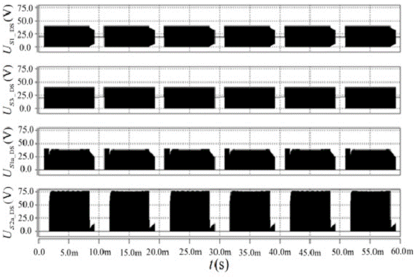
Fig.2
Simulation waveforms of seven-level inverter.(a) Us1_DS, Us3_DS, Us1a_DS
and
Us2a_DS. (b) UC2a, Ud, UX, Uo and io.
(c) Spectrum of Uo.

(a)

(b)

(c)


(d)
Fig.3
Simulation comparison of power decoupling ability at different Cin.
Under proposed control strategy:(a)Ui and Po. (b)Ud and Po.
Under conventional control strategy:(c) Ui and Po. (d) Ud and
Po.
CONCLUSION:
A
bridge modular switched-capacitor-based multilevel inverter with optimized
UFD-SPWM control method is proposed in the paper. The switched-capacitor-based
stage can obtain high conversion efficiency and multiple voltage levels. Meanwhile,
it functions as an active energy buffer, enhancing the power decoupling ability
and conducing to cut the total size of the twice-line energy buffering
capacitance. Furthermore, voltage multi-level in DC-link reduces the switching
loss of inversion stage because turn-off voltage stress of switches changes
with phase of output voltage rather than always suffers from one relatively
high DC voltage. Most importantly, the control method of UFD-SPWM, doubling equivalent
witching frequency, is employed in the inversion stage for a high quality
output waveform with reduced harmonic. In addition, the optimized voltage level
phase maximizes the fundamental component in output voltage pulses to reduce
harmonic backflow as possible. Hence, the comprehensive system efficiency has
been promoted and up to peak value of 97.6%. Finally, two conversion stages are
controlled independently for promoting reliability and decreasing complexity.
In future work, detailed loss discussion, including theoretic calculation and
validation of loss breakdown, will be presented.
REFERENCES:
[1]
M. Jun, "A new selective loop bias mapping phase disposition PWM with
dynamic voltage balance capability for modular multilevel converter," IEEE
Trans. Ind. Electron., vol. 61, no. 2, pp. 798-807, Feb. 2014.
[2]
N. Mehdi, and G. Moschopoulos, "A novel single-stage multilevel type full-bridge
converter," IEEE Trans. Ind. Electron., vol. 60, no. 1, pp. 31-42,
Jan. 2013.
[3]
E. Ehsan and N. B. Mariun, "Experimental results of 47-level switchladder multilevel
inverter," IEEE Trans. Ind. Electron., vol. 60, no. 11, pp.
4960-4967, Nov. 2013.
[4]
J. Lai, “Power conditioning circuit topologies,” IEEE Trans. Ind. Electron.,
vol. 3, no. 2, pp. 24-34, Jun. 2009.
[5]
L. He, C. Cheng, “Flying-Capacitor-Clamped Five-Level Inverter Based on
Switched-Capacitor Topology,” IEEE Trans. Ind. Electron., vol. 63,
no.12, pp. 7814-7822, Sep. 2016.