ABSTRACT:
A three-level common-mode voltage eliminated inverter
with single dc supply using flying capacitor inverter and cascaded H-bridge has
been proposed in this paper. The three phase space vector polygon formed by
this configuration and the polygon formed by the common-mode eliminated states
have been discussed. The entire system is simulated in Simulink and the results
are experimentally verified. This system has an advantage that if one of
devices in the H-bridge fails, the system can still be operated as a normal
three-level inverter at full power. This inverter has many other advantages
like use of single dc supply, making it possible for a back-to-back grid-tied
converter application, improved reliability, etc.
KEYWORDS:
1.
Common-mode
voltage elimination
2.
Hybrid multilevel inverter
3.
Multilevel inverter
4.
Three-level inverter
SOFTWARE: MATLAB/SIMULINK
BLOCK DIAGRAM:

Fig 1 Power circuit for the proposed three level
common mode voltage eliminated inverter
EXPECTED SIMULATION RESULTS:

Fig. 2. Simulation result for testing
the capacitor balancing algorithm. VAO :
pole voltage (100 V/div), IA : pole current (5
A/div) VC 1 : cap1-voltage (100 V/div), VC 2 : cap2 voltage (50 V/div), VC M : common-mode voltage (50 V/div),
time: 500 ms/div.

Fig. 3. Steady-state performance at 10
Hz. VAO : pole voltage (100
V/div), VA N : phase
voltage (100 V/div), VN O : neutral
point voltage (20 V/div), IA : phase current (2 A/div), time: 20 ms/div.

Fig. 4. Steady-state performance at 20 Hz. VAO : pole voltage (100 V/div), VA N : phase voltage (100 V/div), VN O : neutral point voltage (20 V/div), IA : phase
current (2 A/div), time: 10 ms/div.

Fig. 5. Steady-state performance at 30 Hz. VAO : pole voltage (100 V/div), VA N : phase voltage (100 V/div), VN O : neutral point voltage (20 V/div), IA : phase
current (2 A/div), time: 10 ms/div.
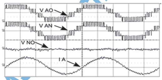
Fig. 6. Steady-state performance at 40 Hz. VAO : pole voltage (100 V/div), VA N : phase voltage (100 V/div), VN O : neutral point voltage (20 V/div), IA : phase
current (2 A/div).
CONCLUSION:
In this paper, a three-level common-mode voltage eliminated inverter with single dc supply using flyin
capacitor inverter and cascaded H-bridge was proposed and
studied. The operation and performance of the proposed inverter is
simulated in Simulink with induction
motor load. Various aspects of the inverter configuration such as the
transients and the performance of the capacitor balancing algorithm, have been studied. The proposed inverter
is implemented in hardware using
IGBT- based inverters. A
three-phase Y-connected induction
motor is run with the proposed inverter and the performance of the drive is
analyzed for both steady-state operation and transient operation during sudden
acceleration. In all the cases, the inverter
was able to give faithful
reproduction of intended voltage levels with negligible capacitor voltage ripple and common
mode, thereby improving the life of bearings. This configuration has
various advantages like motor being
connected in single-ended configuration use of reduced
number of switches, use of single dc supply,
etc. Also, this configuration has
improved reliability.In case of failure of one of the devices in the H-bridge,
the inverter can still be operated
as a normal three-level inverter at full
power or a two-level common-mode
voltage eliminated inverter at full power rating by bypassing the H-bridges, thereby improving the overall reliability of the system
greatly.
REFERENCES:
[1]
L. G. Franquelo, J. Rodriguez, J. I. Leon, S. Kouro, R. Portillo, M.A.M. Prats,
“The age of multilevel
converters arrives,” IEEE
Ind. Electron. Magazine, vol. 2, no. 2, pp. 28–39,
June.2008.
[2]
S. Kouro, M.
Malinowski, K. Gopakumar,
J. Pou, L.
G. Franquelo, B.Wu, J. Rodriguez, M. A. Perez, and J. I.
Leon, “Recent Advances and Industrial Applications
of Multilevel Converters,” IEEE
Trans. Ind. Electron.,vol. 57, no. 8, pp.
2553–2580, Aug. 2010.
[3]
A. Nabae, I. Takahashi,
and H. Akagi, “A new
neutral-point-clamped PWM
inverter,” IEEE Trans. Ind. Appl., vol. IA-17, no. 5, pp. 518–523, Sep. 1981.
[4]
M. Marchesoni, M. Mazzucchelli, and S. Tenconi, “A non-conventional power
converter for plasma
stabilization,” in Proc.
IEEE 19th Annu. Power
Electron. Spec. Conf. (PESC’88) Rec., Apr. 11–14,
vol. 1, pp. 122–129.
[5]
Z. Du,
L.M. Tolbert, J. N. Chiasson,
B. Ozpineci, H. Li, and
A. Q. Huang,
“Hybrid cascaded H-bridges
multilevel motor drive control for electric
vehicles,” in Proc. IEEE 37th Power Electron. Spec. Conf., Jun. 18–22, 2006, pp. 1–6.